© 2014 National Instruments. All rights reserved.
373419A-01
Apr14
Refer to the
NI Trademarks and Logo Guidelines
at
ni.com/trademarks
for more information on National Instruments trademarks. Other
product and company names mentioned herein are trademarks or trade names of their respective companies. For patents covering National
Instruments products/technology, refer to the appropriate location:
Help»Patents
in your software, the
patents.txt
file on your media, or the
National Instruments Patents Notice
at
ni.com/patents
. You can find information about end-user license agreements (EULAs) and third-party
legal notices in the readme file for your NI product. Refer to the
Export Compliance Information
at
ni.com/legal/export-compliance
for the National Instruments global trade compliance policy and how to obtain relevant HTS codes, ECCNs, and other import/export data. NI MAKES
NO EXPRESS OR IMPLIED WARRANTIES AS TO THE ACCURACY OF THE INFORMATION CONTAINED HEREIN AND SHALL NOT BE LIABLE FOR
ANY ERRORS. U.S. Government Customers: The data contained in this manual was developed at private expense and is subject to the applicable
limited rights and restricted data rights as set forth in FAR 52.227-14s, DFAR 252.227-7014, and DFAR 252.227-7015.
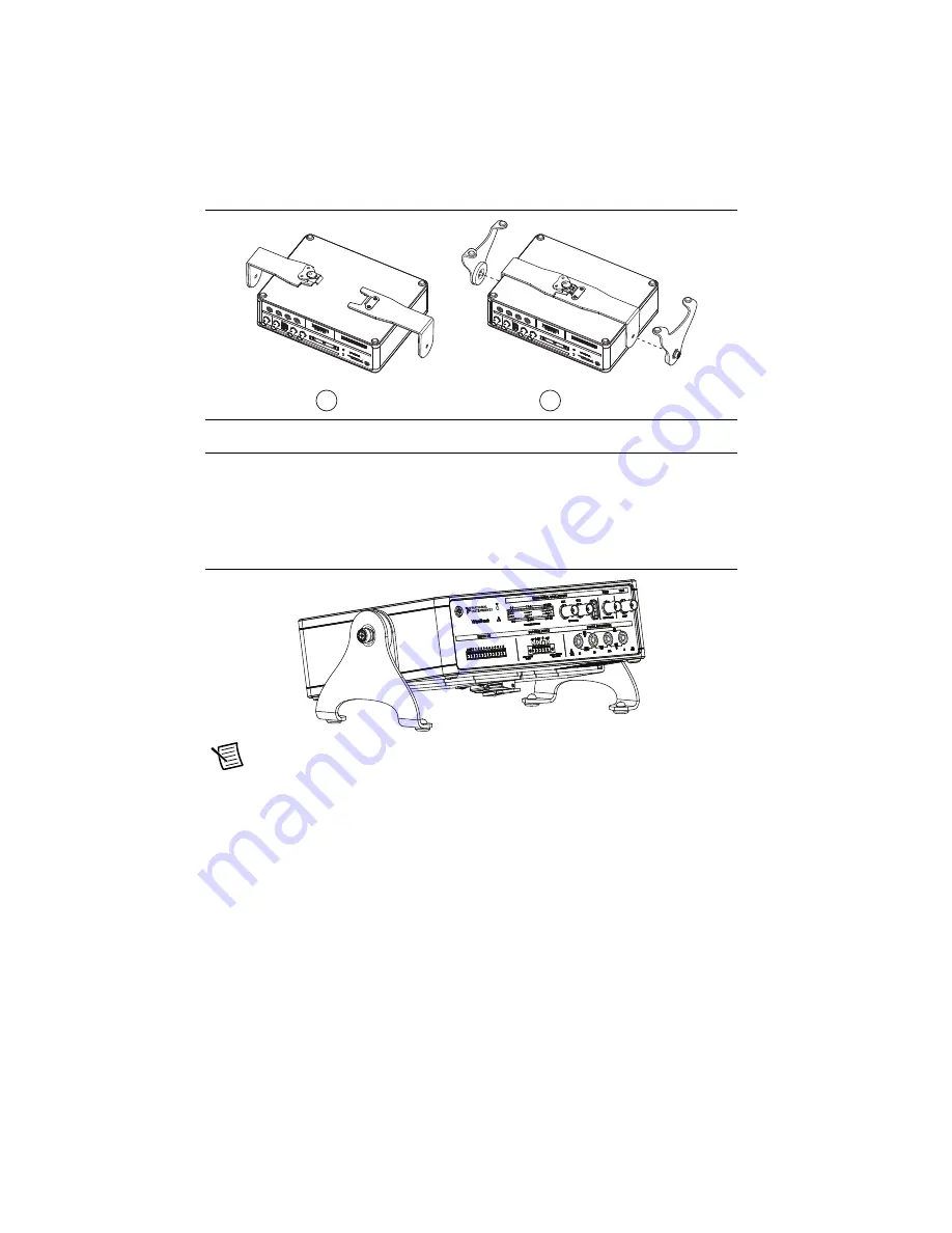
Figure 2.
Installing the Brackets
5.
Align the captive screws on the end brackets with the holes of the bottom brackets and
lightly tighten the screws, as shown in Figure 2.
6.
Turn the VirtualBench face up and use your fingers and/or a #2 screwdriver to adjust the
angle of the VirtualBench as needed.
Figure 3.
VirtualBench and the Desktop Mounting Kit
Note
The desktop mounting kit will lift your VirtualBench off the surface of the
table by approximately 38 mm (1.5 in.). Total height will vary depending on the angle
that you set the feet. Allow for at least 23 mm (0.9 in.) on each side of VirtualBench
to accommodate for the end brackets.
1
Aligning the Two Bottom Brackets
2
Installing the Captive Screws of the End Brackets into the Holes of the Bottom Brackets
1
2


