


Notice
Never touch the exposed pins of connectors.
Note
Do not install a device if it appears damaged in any way.
3. Unpack any other items and documentation from the kit.
Store the device in the antistatic package when the device is not in use.
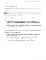
Verifying the Kit Contents
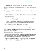
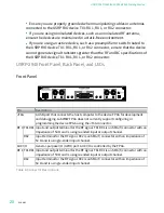
Figure 1. Kit Contents
LINK
PWR
TX OUTPUT MAX +20 dBm, RX INPU
T MAX -15 dBm, ALL RF POR
TS 50 W
TX1 RX1
RX2
GPS
PPS
REF
TX1 RX1
RX2
AUX I/O
3.3 VDC MAX
RF 0
RF 1
NI USRP-2943R
1.2 GHz - 6 GHz
NI USRP-2943R
1.2 GHz - 6 GHz
Designed by Ettus Research
Designed by Ettus Research
JTAG
1
5
4
3
2
1. USRP RIO Device
2. SMA Driver Bit (USRP-2945 Only)
3. Getting Started Guide (This Document) and Safety, Environmental, and
Regulatory Information Document
4. SMA (m)-to-SMA (m) Cable
5. 30 dB SMA Attenuator (Not Included with USRP-2945)
Notice
If you directly connect or cable a signal generator to your device,
or if you connect multiple devices together, you must connect a 30 dB
attenuator to the RF input (RX1 or RX2) of each receiving USRP RIO device.
© National Instruments
5
USRP-2940/2942/2943/2944/2945 Getting Started


