background image

transients greater than the RF and DC specifications of the USRP device TX 1 RX 1 or
RX 2 connector.

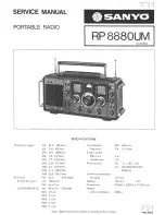
USRP-2930 Front Panel, Back Panel, and LEDs

Front Panel

MIMO EXPANSION

GB ETHERNET

RX 1 
TX 1

REF IN

PPS IN

A
C
E

B
D
F

NI USRP-2930

50 MHz - 2.2 GHz

RX 2

POWER

6 V      3 A

Table 5. Connector Descriptions

Connector

Use


RX1

TX1

Input and output terminal for the RF signal. RX1 TX1 is an SMA (f)
connector with an impedance of 50 Ω and is a single-ended input or
output channel.

RX2

Input terminal for the RF signal. RX2 is an SMA (f) connector with
an impedance of 50 Ω and is a single-ended input channel.

REF IN

This terminal is not used for this device.

PPS IN

Input terminal for the PPS timing reference. PPS IN is an SMA (f)
connector with an impedance of 50 Ω and is a single-ended input
channel. PPS IN accepts 0 V to 3.3 V TTL and 0 V to 5 V TTL
signals.

MIMO
EXPANSION

The MIMO EXPANSION interface port connects two USRP devices
using a compatible MIMO cable.

GB ETHERNET

The gigabit Ethernet port accepts an RJ-45 connector and gigabit
Ethernet compatible cable (Category 5, Category 5e, or Category 6).

POWER

The power input accepts a 6 V, 3 A external DC power connector.

Table 6. LED Indicators

LED

Description

Color

Indication


A

Indicates the transmit status of the
device.

Off

The device is not transmitting data.

Green

The device is transmitting data.

16

  | 

ni.com

  | 

USRP-2930/2932 Getting Started Guide

Summary of Contents for USRP-2930

Page 1: ...Guidelines 4 Environmental Characteristics 4 Installing the Software 4 Installing the Software Using NI Package Manager 4 Installing the Software Using the Driver Download Page 5 Installing the Device...

Page 2: ...arge ESD from damaging the device ground yourself using a grounding strap or by holding a grounded object such as your computer chassis 1 Touch the antistatic package to a metal part of the computer c...

Page 3: ...nts you must provide a computer with available gigabit Ethernet interface Optional Items LabVIEW Modulation Toolkit MT available for download at ni com downloads and included in LabVIEW Communications...

Page 4: ...Software You must be an Administrator to install NI software on your computer 1 Install an application development environment ADE such as LabVIEW or LabVIEW Communications System Design Suite 2 Follo...

Page 5: ...pts to complete the installation 4 When the installer completes select Shut Down in the dialog box that prompts you to restart shut down or restart later Installing the Device Install all the software...

Page 6: ...utputs MIMO Expansion Configuring the Device Setting Up the Network Ethernet Only The device communicates with a host computer over gigabit Ethernet Set up the network to enable communication with the...

Page 7: ...address of the device and you must configure the network 1 Verify that your device is powered on and connected to your computer using the gigabit Ethernet interface 2 Select Start All Programs Nation...

Page 8: ...ted then click the Refresh Devices List button to scan for USRP devices Configuring Multiple Devices with Ethernet You can connect multiple devices in the following ways Multiple Ethernet interfaces O...

Page 9: ...llows a single gigabit Ethernet adapter on the computer to interface with multiple USRP devices connected to the switch Assign the host Ethernet interface a subnet and assign each device an address in...

Page 10: ...ther software defined radio SDR functionality Note You can access additional examples from the Code Sharing Community at ni com usrp From the Start menu at Start All Programs National Instruments NI U...

Page 11: ...st to confirm that the device transmits and receives signals and is connected correctly to the host computer 1 Attach the included 30 dB attenuator to one end of the SMA m to SMA m cable 2 Connect the...

Page 12: ...e to update the devices Updating Device Firmware and FPGA Images Optional The firmware and FPGA images for USRP devices are stored in the device internal memory You can reload the FPGA image or firmwa...

Page 13: ...et correctly 11 Close the utility Related Information Refer to the Load the Images onto the On board Flash USRP N Series Only section of the UHD USRP2 and N Series Application Notes Why Doesn t the US...

Page 14: ...192 168 10 2 in the command prompt where 192 168 10 2 is the IP address for your USRP device 4 Press Enter If the uhd_find_devices command does not return the listing for your device the firewall may...

Page 15: ...Changing the IP Address on page 7 Why Does the Device Not Connect to the Host Interface The host Ethernet interface must be a gigabit Ethernet interface to connect to the USRP device Ensure the connec...

Page 16: ...F IN This terminal is not used for this device PPS IN Input terminal for the PPS timing reference PPS IN is an SMA f connector with an impedance of 50 and is a single ended input channel PPS IN accept...

Page 17: ...ff The firmware is not loaded Green The firmware is loaded E Indicates the reference lock status of the LO on the device Off There is no reference signal or the LO is not locked to a reference signal...

Page 18: ...S IN Input terminal for the PPS timing reference PPS IN is an SMA f connector with an impedance of 50 and is a single ended input channel PPS IN accepts 0 V to 3 3 V TTL and 0 V to 5 V TTL signals MIM...

Page 19: ...ff The firmware is not loaded Green The firmware is loaded E Indicates the reference lock status of the LO on the device Off There is no reference signal or the LO is not locked to a reference signal...

Page 20: ...plete resource for technical support At ni com support you have access to everything from troubleshooting and application development self help resources to email and phone assistance from NI Applicat...

Page 21: ...EULAs and third party legal notices in the readme file for your NI product Refer to the Export Compliance Information at ni com legal export compliance for the NI global trade compliance policy and h...

Reviews: