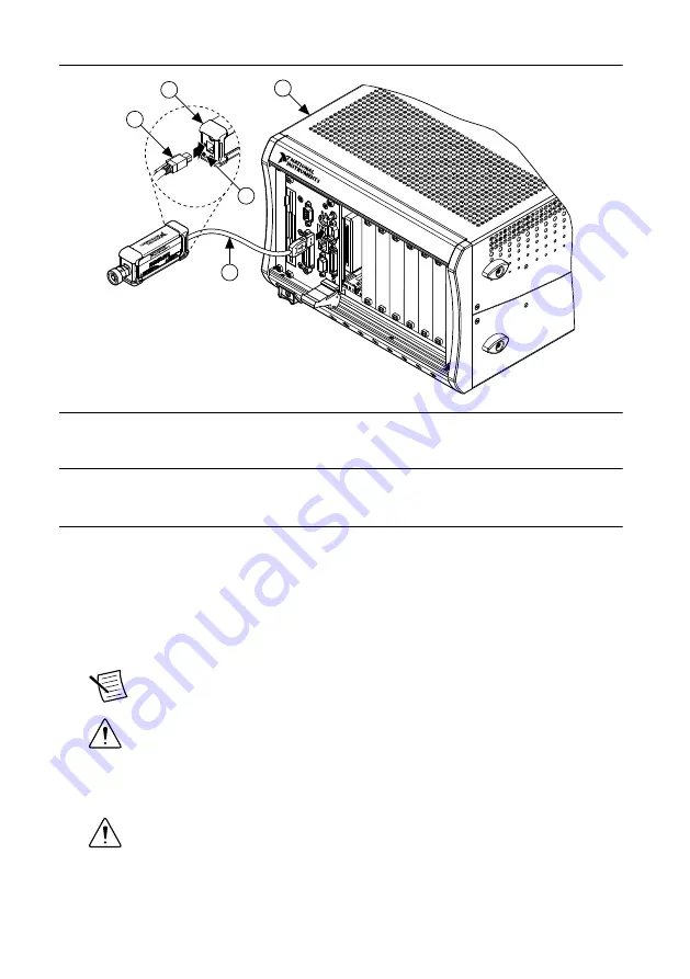
background image

Figure 1.

 Installing the NI 5684

NI PXI-1042

2

1

3

NI USB-568x

5

4

1. PXI Chassis
2. USB Cable
3. Mini-B USB Port

4. Mini-B USB connector
5. NI RF Power Meter Back Panel

Connecting the Device Under Test

NI recommends that you zero the NI RF power meter after connecting to a USB port and
before taking power measurements. If you make frequent low-power measurements, zero the
power meter often.
1.

Connect the NI RF power meter to a computer or chassis.

2.

Zero the NI RF power meter.

3.

Connect the Type-N front panel connector to the RF source connection.

Note


You may need to use the included Type-N-to-SMA adapter, depending

on the RF source connection.

Caution


Always refer to the specifications document before connecting

signals. Failure to observe the specified maximum signal ratings can cause
shock, a fire hazard, or damage to the devices connected to the NI RF power
meter. NI is not liable for any damage or injuries resulting from incorrect signal
connections.

Caution


Do not turn the sensor body when mating the connectors. Always

use the specified torque wrench. Do not over-torque the connectors.

4.

The back panel LED indicates the status of the NI RF power meter. To confirm that the
device is properly connected, refer to the following table for LED information.

NI 5684 Getting Started Guide

  | 

© National Instruments

  | 

5

Summary of Contents for USB-5684

Page 1: ...4 if you use it in a manner not described in this document Contents Electromagnetic Compatibility Guidelines 1 Verifying the System Requirements 2 Unpacking the Kit 2 Verifying the Kit Contents 3 Prep...

Page 2: ...ft Caution To ensure the specified EMC performance the length of the USB cable must be no longer than 30 m 100 ft Verifying the System Requirements To use the NI 5684 your system must meet certain re...

Page 3: ...ontents you need the following items 1 N m torque wrench Desktop computer laptop or chassis with one available USB 2 0 or USB 1 1 compliant slot Preparing the Environment Ensure that the environment y...

Page 4: ...see access and security messages during installation Accept the prompts to complete the installation 4 When the installer completes select Restart in the dialog box that prompts you to restart shut d...

Page 5: ...ay need to use the included Type N to SMA adapter depending on the RF source connection Caution Always refer to the specifications document before connecting signals Failure to observe the specified m...

Page 6: ...l 3 1 2 4 1 Status LED 2 External Trigger In Terminal 3 USB 2 0 A to Mini B Port 4 External Trigger Out Terminal Note External Trigger Out capability is currently unsupported Connector Care and Handli...

Page 7: ...ermanently damages the internal components Before making connections verify the maximum input levels labeled below the ports on the module front panel Avoid Mechanical Shock Precision connectors are d...

Page 8: ...e device is still not listed power off the system ensure the device is correctly installed and restart 3 Record the device identifier MAX assigns to the hardware Use this identifier when programming t...

Page 9: ...n modify an NI 568x C example to create an application with Microsoft Visual C C and all required include and library files are automatically added to the project C or LabWindows CVI Available at Prog...

Page 10: ...pport ni com support RF Solutions ni com rf Updates ni com updates Services ni com services Getting Started with LabVIEW Getting Started with LabWindows CVI Located using the NI Example Finder Located...

Page 11: ...oC for your product by visiting ni com certification If your product supports calibration you can obtain the calibration certificate for your product at ni com calibration National Instruments corpora...

Page 12: ...and third party legal notices in the readme file for your NI product Refer to the Export Compliance Information at ni com legal export compliance for the National Instruments global trade compliance p...

Reviews: