


©
National Instruments Corporation
4-1
4
Register Descriptions
This chapter describes in detail the SCXI-1121 Module ID Register, the
Configuration Register, the Slot 0 registers, and multiplexer addressing.
Note
If you plan to use a programming software package such as NI-DAQ, LabWindows,
or LabVIEW with your SCXI-1121 board, you do not need to read this chapter.
Register Description
Register Description Format
The register description chapter discusses each of the SCXI-1121 registers
and the Slot 0 registers. A detailed bit description of each register is given.
The individual register description gives the type, word size, and bit map
of the register, followed by a description of each bit.
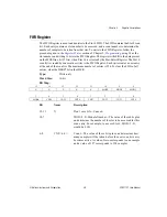
The register bit map shows a diagram of the register with the MSB shown
on the left (bit 15 for a 16-bit register, bit 7 for an 8-bit register), and the
LSB shown on the right (bit 0). A rectangle is used to represent each bit.
Each bit is labeled with a name inside its rectangle. An asterisk (*) after the
bit name indicates that the bit is inverted (negative logic). The Module ID
register has a unique format described in the
In many of the registers, several bits are labeled with an X, indicating don’t
care bits. When you write to a register you may set or clear these bits
without effect.
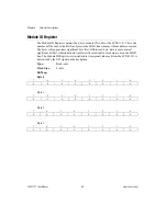
SCXI-1121 Registers
The SCXI-1121 has two registers. The Module ID Register is a four-byte,
read-only register that contains the Module ID number of the SCXI-1121.
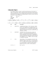
The Configuration Register is a 16-bit, write-only register that controls the
functions and characteristics of the SCXI-1121.


