background image

Chapter 3

Configuring Your SCXI Hardware and Software

Getting Started with SCXI

3-34

www.ni.com

SCXI-1520 Module

The SCXI-1520 is an 8-channel module used to interface with strain gauges
and strain-gauge-based sensors.

You can set the bridge excitation voltage, hardware null setting, filter cutoff
frequency, or shunt calibration settings on a per-channel basis through
software control. You can set the gain of each input channel through
LabVIEW or NI-DAQ. An onboard EEPROM contains gain and offset
calibration constants for each channel. NI-DAQ and LabVIEW
automatically use these constants to correct for amplifier gain and offset
errors when scaling data.

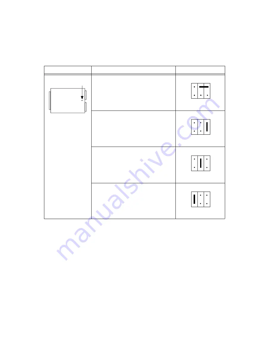
Table 3-26.

SCXI-1141/1142/1143 Grounding and Shielding Jumper Configuration

Jumper

Description

Configuration

Parking position. Use this setting with DAQ
devices in DIFF mode (factory-default
position).

Use this position for DAQ devices with SE
inputs, such as the Lab and 1200 devices,
DAQCard-700, or MIO and AI devices in
RSE mode.

Connects the SCXIbus guard to the analog
reference.

Select this position for MIO and AI devices
in NRSE mode.

W2

W2

R2 R1 R0

B

A

W2

B

A

R2 R1 R0

W2

B

A

R2 R1 R0

W2

B

A

R2 R1 R0

Summary of Contents for SCXI-1000

Page 1: ...SCXI Getting Started with SCXI Getting Started with SCXI July 2000 Edition Part Number 320515F 01...

Page 2: ...many 089 741 31 30 Greece 30 1 42 96 427 Hong Kong 2645 3186 India 91805275406 Israel 03 6120092 Italy 02 413091 Japan 03 5472 2970 Korea 02 596 7456 Mexico D F 5 280 7625 Mexico Monterrey 8 357 7695...

Page 3: ...he National Instruments installation operation or maintenance instructions owner s modification of the product owner s abuse misuse or negligent acts and power failure or surges fire flood accident ac...

Page 4: ...rds 1 13 DAQ Modules 1 13 SCXI Cable Assemblies 1 14 SCXI Multichassis System with Plug In DAQ Device 1 14 Optional Software 1 15 Overview of SCXI Operation 1 17 Analog Input Modules 1 17 Analog and D...

Page 5: ...40 Module 3 29 DAQ Device Connections in Multiple Module Systems 3 29 User Configurable Jumpers and DIP Switches 3 29 SCXI 1141 SCXI 1142 and SCXI 1143 Modules 3 32 SCXI 1520 Module 3 34 SCXI 1530 153...

Page 6: ...cks 4 4 Onboard Temperature Sensors for Cold Junction Compensation 4 5 Opening the SCXI 13XX Terminal Block 4 6 Connector and Shell Assemblies 4 7 Connecting Transducers to the SCXI System 4 7 Thermoc...

Page 7: ...I Module Grounding Screw 3 1 Figure 3 2 Removing the SCXI Module Cover 3 2 Figure 3 3 Scanning Techniques 3 26 Figure 3 4 SCXI 1200 Front Connector Pin Assignments 3 55 Figure 3 5 SCXI 2400 Module Def...

Page 8: ...s Table 1 1 SCXI Modules 1 6 Table 1 2 Direct Mount Terminal Blocks 1 9 Table 1 3 TBX Terminal Blocks for SCXI 1 12 Table 1 4 SCXI Cable Assemblies 1 14 Table 3 1 SCXI 1100 Input Signal Referencing Ju...

Page 9: ...Configuration 3 39 Table 3 30 SCXI 1162 Communication Mode Configuration 3 40 Table 3 31 SCXI 1162 Parallel Lines Jumper Configuration 3 41 Table 3 32 SCXI 1162 Device Type Jumper Configuration 3 42...

Page 10: ...ion This icon denotes a note which alerts you to important information This icon denotes a caution which advises you of precautions to take to avoid injury data loss or a system crash This icon denote...

Page 11: ...grams subprograms subroutines device names functions operations variables filenames and extensions and code excerpts NI DAQ Refers to the NI DAQ driver software unless otherwise noted PXI Refers to PC...

Page 12: ...tation As you read this manual you may find it helpful to refer to the following documents Your SCXI chassis module terminal block connector and shell and cable assembly user manuals or installation g...

Page 13: ...in DAQ device for analog to digital conversion The plug in DAQ device also controls and monitors the operation of digital I O and analog output modules in the SCXI system You can monitor and control u...

Page 14: ...1140 SCXI 1140 SCXI 1140 SC XI 100 1 MAIN FRAM E SC XI SCXI Signal Conditioning and DAQ Modules a Front End Signal Conditioning for Plug In DAQ Device Parallel Port Link b External DAQ System SCXI 114...

Page 15: ...DAQ device if using any analog input SCXI modules SCXI cable assembly Your computer NI DAQ driver software for PC compatibles or Macintosh One of the following software packages LabVIEW for Macintosh...

Page 16: ...digital bus and a chassis controller that regulates bus operation as shown in Figure 1 3 The analog bus transfers analog signals from all resident analog input modules to the DAQ device using a connec...

Page 17: ...ignals Some modules have excitation potentials or currents and half bridge completion networks for transducers such as strain gauges or resistive temperature devices RTDs Digital modules isolate digit...

Page 18: ...124 Analog output 6 channel isolated D A converter SCXI 1125 Analog input Jumperless SCXI 1120 SCXI 1126 Analog input 8 channel isolated frequency to voltage converter SCXI 1140 Analog input 8 channel...

Page 19: ...nterparts Figure 1 4 shows the terminal block options and Table 1 2 lists the modules with which they work Table 1 3 lists the TBX terminal blocks and the modules with which they work Several terminal...

Page 20: ...CXI Getting Started with SCXI 1 8 www ni com Figure 1 4 Terminal Block Options b TBX Terminal Block a SCXI Direct Mount Terminal Block SCXI Chassis TBX Terminal Block Shielded Cable SCXI Chassis Direc...

Page 21: ...oupleconnectors built inCJC sensor per channel SCXI 1120 D SCXI 1121 SCXI 1125 SCXI 1320 Terminal block Yes SCXI 1321 for SCXI 1121 Terminal block Yes Offset nulling and shunt calibration for strain g...

Page 22: ...or and shell assembly SCXI 1160 SCXI 1324 Terminal block No SCXI 1161 No terminal block screw terminals in module SCXI 1162 1162HV SCXI 1163 1163R SCXI 1326 Terminal block No SCXI 1180 SCXI 1302 Termi...

Page 23: ...A N A Serial communication module 1 The SCXI 1303 SCXI 1322 SCXI 1327 and SCXI 1328 use an onboard thermistor for sensing cold junction temperature Other terminal blocks use an IC temperature sensor 2...

Page 24: ...quired Cables 1100 1102 B C 1120 D 1121 1125 1122 1124 1140 1141 1142 1143 1160 1161 1162 1162HV 1163 1163R 1180 1181 1181 K 1200 TBX 1303 1 SH96 96 or R96 96 TBX 1328 1 SH32 32 A TBX 1325 SH48 48 A T...

Page 25: ...sisting of any combination of analog and digital SCXI modules Use MIO and AI devices for systems that require high speed hardware controlled scanning You can use all E Series AT PCMCIA PCI and PXI bus...

Page 26: ...abled using an SCXI 1346 or SCXI 1350 chassis are daisy chained using multichassis adapters with shielded or unshielded cables to a single plug in DAQ device You can control up to eight SCXI 1000 SCXI...

Page 27: ...are ships with your National Instruments DAQ device SCXI 1200 SCXI 2000 or SCXI 2400 NI DAQ has a library of functions that you can call from your application development environment ADE Alternatively...

Page 28: ...ual Basic Whether you are using conventional programming languages LabVIEW LabWindows CVI or ComponentWorks your application uses the NI DAQ driver software as illustrated in Figure 1 6 Figure 1 6 The...

Page 29: ...nes on the DAQ device control the modules and chassis The DAQ device uses three or four digital output lines and the EXTSTROBE line to program the SCXI system In addition a digital input line is used...

Page 30: ...chronizes the SCXI multiplexing with the internal clock that triggers the A D conversions on the DAQ device SCXI Slot 0 enables and disables the modules according to the preprogrammed list In this way...

Page 31: ...t the state of the digital output lines or relays or serially reads patterns from the modules to determine the state of the digital input lines In parallel mode each SCXI digital I O line corresponds...

Page 32: ...SCXI system 1 You receive NI DAQ software with your DAQ device SCXI 1200 SCXI 2400 or SCXI 2000 If you are using LabWindows CVI install LabWindows CVI first Next install NI DAQ for PC compatibles and...

Page 33: ...ule If the module does not connect smoothly check that it is aligned correctly 2 Tighten the thumbscrews finger tight Do not over tighten 3 Repeat steps 1 and 2 until you have installed all of your mo...

Page 34: ...modules in the chassis can access the track and hold counter signal through the SCXIbus in the chassis backplane b If you are not using an SCXI 1140 and are using one or more SCXI 110X module connect...

Page 35: ...able assembly attached to the SCXI module and chassis Figure 2 1 Attaching the SCXI Cable Assembly to the SCXI Module and Chassis S C X I Female Connector to DAQ Device Female Connector to Module Rear...

Page 36: ...conditioned signals using an SCXI 1180 feedthrough panel or SCXI 1181 breadboard module Cable assemblies also have an integral rear panel that you can fasten to the SCXI chassis with two screws Using...

Page 37: ...ck of the SCXI 1200 and the SCXI 2000 chassis Note If your SCXI chassis includes only analog output and digital I O modules you do not need the SCXI 1200 module The SCXI 2000 and SCXI 2400 can communi...

Page 38: ...National Instruments software Module Configuration You may need to configure your SCXI modules before using them in your application Some SCXI modules have a number of user configurable jumpers that y...

Page 39: ...ver To replace the cover follow these steps 1 Align the cover with the slot at the top of the module and snap the bottom of the cover into place 2 Replace the grounding screw taking care not to over t...

Page 40: ...asuring This section begins with a description of the main types of signals Ground Referenced and Floating Signal Sources Signal sources are either ground referenced or floating A ground referenced so...

Page 41: ...loating or nonreferenced and you want to ground reference the signals through a 100 k resistor installed in the module however it is best to ground reference the signals at the source or at the termin...

Page 42: ...renced or have high leakage to ground a ground loop can result causing DC offsets or noise 2 Configure the filtering The SCXI 1100 has two lowpass one pole resistance capacitor RC filters with bandwid...

Page 43: ...lter is applied after the signal is multiplexed the sample rate or channel rate must be low enough for the filter to settle to the required accuracy Table 3 2 shows the maximum recommended aggregate s...

Page 44: ...SCXI 1102 SCXI 1102 B and SCXI 1102 C have lowpass filters with cutoff frequencies of 2 Hz 200 Hz and 10 kHz respectively The SCXI 1102 works only in multiplexed mode and drives a single analog input...

Page 45: ...104C inputs to a single output which drives a single DAQ device channel SCXI 1112 Module The SCXI 1112 module is an 8 channel module designed for measuring temperature using thermocouples Each of the...

Page 46: ...of the previous conditions applies to you The SCXI 1120 D has 42 user configurable jumpers many of which perform the same function but configure different channels You can set the jumpers to configure...

Page 47: ...f your module move the appropriate jumper on your module to the position indicated in Table 3 5 To determine the overall gain of a given channel on the SCXI 1120 use the following formula To determine...

Page 48: ...g eliminates the noise generated by the isolation amplifier producing a higher signal to noise ratio Furthermore two filter bandwidths are available 10 kHz and 4 Hz Second stage 1 A 2 B 5 C 10 D facto...

Page 49: ...ated section of your input channel Two stage filtering eliminates the noise generated by the isolation amplifier producing a higher signal to noise ratio Furthermore two filter bandwidths are availabl...

Page 50: ...ode Position 2 3 for DTEMP direct mode is no longer supported by the current version of the SCXI 1320 terminal block 4 Configure the amplifier output referencing mode The signal output referencing is...

Page 51: ...values of 4 Hz or 10 kHz and individually configurable jumper selectable channel gains of 1 2 5 10 20 50 100 200 500 1 000 and 2 000 The SCXI 1121 module has 45 user configurable jumpers Position the...

Page 52: ...ransducers require half bridge completion circuitry You are using digital modules and are cabling the SCXI 1121 to a DAQ device Read the rest of this section on the SCXI 1121 module if any of the prev...

Page 53: ...ing is also two stage and is jumper selectable for each channel The SCXI 1121 uses a two stage filtering configuration to achieve a higher signal to noise ratio Filter bandwidth does not affect the ma...

Page 54: ...g whereas setting the jumper to an odd number for example W7 sets the second stage of the same channel to 10 kHz filtering Refer to Table 3 11 for the jumper and channel correspondence for filtering 3...

Page 55: ...Excitation Mode Jumper Configuration Jumpers Excitation Channel Voltage Mode Factory Default Position Current Mode 0 1 2 3 W14 W15 1 2 3 W14 1 2 3 W15 1 2 3 W14 1 2 3 W15 W22 W23 1 2 3 W22 1 2 3 W23...

Page 56: ...er channel W16 W24 W25 W26 W36 W37 W48 and W49 If you select voltage mode you can apply a potential difference of either 3 333 V or 10 00 V If you select current mode you can apply an excitation curre...

Page 57: ...ation Level Jumper Configuration Jumpers Excitation Channel 3 333 V or 0 150 mA Factory Default Position 10 V or 0 450 mA 0 1 2 3 W16 W26 1 2 3 W16 1 2 3 W26 1 2 3 W16 1 2 3 W26 W24 W25 1 2 3 W24 1 2...

Page 58: ...ient of 5 ppm C You can enable the network on an individual channel basis using two additional jumpers per channel W1 W2 W17 W18 W27 W28 W39 and W40 When you enable the completion network you automati...

Page 59: ...XI 1121 Half Bridge Completion Network Jumper Configuration Jumpers Channel Enable Network Disable Network Factory Default Position 0 1 2 3 W1 W2 1 2 3 A B W2 W1 1 2 3 A B W2 W1 W17 W18 1 2 3 A B W18...

Page 60: ...two isolated excitation channels The SCXI 1122 is a module for signal conditioning of strain gauges RTDs thermistors thermocouples volt and millivolt sources 4 to 20 mA current sources and 0 to 20 mA...

Page 61: ...the following procedure to configure your SCXI 1122 module Note If the module is not connected to a DAQ device the position of W2 is irrelevant 1 When using a single chassis set jumper W2 in position...

Page 62: ...Specifications of the SCXI 1122 User Manual To avoid mechanical wear on the relays when the SCXI 1122 is used for continuous multichannel scanning you should acquire n samples on a given channel befo...

Page 63: ...ab and 1200 devices and DIO devices You can control several SCXI 1124s in a single chassis with one DAQ device and in combination with other SCXI module types Note If nothing is connected to the SCXI...

Page 64: ...bling this module directly to a DAQ device set jumpers W1 W2 and W3 depending on the type of DAQ device you are using as shown in Table 3 20 Table 3 19 SCXI 1124 Chassis Jumper Configuration Jumper De...

Page 65: ...SCXI 1125 module is exactly like the SCXI 1120 D with the exception that it is software configurable and does not have any jumpers Use Measurement Automation Explorer to configure the gain and filter...

Page 66: ...device you must connect the SCXI 1140 to the DAQ device because the SCXI 1140 requires a counter timer signal from the DAQ device to control the module track and hold circuitry Other modules do not us...

Page 67: ...al referencing modes Table 3 21 lists the SCXI 1140 signal referencing configurations 2 Configure the instrumentation amplifier output referencing mode The output referencing mode is relevant only if...

Page 68: ...he factory default position sets the gain to 1 that is all four bits of each DIP switch are set to the off position number side up Select other gains by setting one or more of the four bits of a parti...

Page 69: ...for antialiasing applications as well as for general purpose amplification and filtering of signals The SCXI 1141 SCXI 1142 and SCXI 1143 have two user configurable jumpers Jumper W1 is set at the fa...

Page 70: ...prevent this set jumper W1 to position P on only one of the SCXI 1141 1142 1143 modules that are connected to the DAQ device in a multiple chassis system It does not matter which of the SCXI 1141 1142...

Page 71: ...ns gain and offset calibration constants for each channel NI DAQ and LabVIEW automatically use these constants to correct for amplifier gain and offset errors when scaling data Table 3 26 SCXI 1141 11...

Page 72: ...ou can turn the 4 mA current excitation on or off You can set the bandwidth of the four pole Bessel filter to 2 5 5 10 or 20 kHz You can set the gain to 1 10 or 100X All channels are simultaneously sa...

Page 73: ...rement Automation Explorer or through function calls to NI DAQ Digital SCXI Modules In addition to analog SCXI modules National Instruments produces a variety of digital modules the SCXI 1160 SCXI 116...

Page 74: ...Q device you must connect any other modules in the chassis in either parallel or serial mode to a different DAQ device The only exception to this rule is the DIO 96 PnP which can work with two digital...

Page 75: ...is connected to an analog device or a DIO device as shown in Table 3 28 SCXI 1161 Module The SCXI 1161 module controls eight SPDT relays The module has three user configurable jumpers for configuring...

Page 76: ...for configuring the operating mode and the type of DAQ device connected to your module Leave all other jumpers in the factory default positions The SCXI 1162 module is shipped configured for use with...

Page 77: ...o parallel mode you can use jumper W1 to select whether the module transfers 24 or 32 parallel lines of data to the device If you are using a DIO 24 or the digital connector pins 51 through 100 of an...

Page 78: ...PnP device Set the jumpers to the MIO position if the module is connected to an AI or MIO device or Lab 1200 device If you are using the SCXI 1162 in parallel mode set jumper W6 to the PAR position I...

Page 79: ...nnects a 2 2 k pullup resistor to the SERDATOUT line An open collector driver either actively drives low or goes to a high impedance state relying on a pullup resistor to make the signal line go high...

Page 80: ...DIO 32 or DIO 96 PnP device S Use this setting to configure the rear connector for serial communication factory default position P Use this setting to configure the rear connector for parallel commun...

Page 81: ...gured for use with a DIO device in serial mode Pullup Use this setting for a single chassis system or for the first chassis in a multichassis system Connects a pullup resistor to the SERDATOUT line fa...

Page 82: ...ectly to a DAQ device the positions of W2 and W3 are irrelevant Table 3 34 shows the SCXI 1163 device type jumper configurations 2 Select serial or parallel mode If you are using the module in paralle...

Page 83: ...configure the module in serial mode factory default position P Use this setting to configure the rear connector for a DIO device in parallel mode DIO Use this setting to configure the module in seria...

Page 84: ...with MIO and AI devices Lab 1200 devices and DIO devices You can control several SCXI 1163R modules in serial mode in a single chassis with one DAQ device Alternatively you can control 24 of the soli...

Page 85: ...ion Configuration for DIO Device Configuration for MIO Device Configures rear connector Factory default position is for DIO devices Configures rear connector Factory default position is for DIO device...

Page 86: ...SERDATOUT line the drivers cannot drive the line low To prevent this set jumper W4 to position A on only one of the SCXI 1163R modules that are connected to the DAQ device in a multichassis system It...

Page 87: ...Port Interface If you plan to connect the SCXI 1200 directly to the parallel port of your computer read this section carefully An IBM compatible computer can support up to three parallel printer ports...

Page 88: ...Analog I O Configuration The SCXI 1200 is shipped from the factory with the following configuration RSE input mode 5 V analog input range bipolar 5 V analog output range bipolar Table 3 38 lists all t...

Page 89: ...g is recommended In this mode data values written to the analog output channel range from 0 to FFF hex 4 095 decimal Analog Input Configuration The SCXI 1200 has three different input modes RSE NRSE a...

Page 90: ...on mode voltage is subsequently subtracted by the input instrumentation amplifier The NRSE configuration is useful for measuring ground referenced signal sources Considerations for using the NRSE conf...

Page 91: ...decimal and 5 V corresponds to 7FF hex 2 047 decimal If you select a unipolar mode the straight binary coding is recommended In this mode 0 V input corresponds to 0 hex and 10 V corresponds to FFF he...

Page 92: ...Pin Assignments PC3 PC2 PC1 PC0 PB7 PB6 PB5 PB4 PB3 PB2 PB1 PB0 PA7 PA6 PA5 PA4 PA3 PA2 PA1 PA0 DGND DAC1OUT AGND ACH6 ACH4 ACH2 ACH5 AISENSE AIGND ACH7 PC4 PC5 PC6 PC7 EXTTRIG OUTB0 EXTCONV 5 V CLKB2...

Page 93: ...nected to the DAQ device to ensure easy connection to the cable assembly Other uses for the SCXI 1180 are described in the SCXI 1180 1181 User Manual SCXI 1181 Breadboard Module The SCXI 1181 module h...

Page 94: ...es on the front panel to select the baud rate for serial communication and the address when used with an RS 485 connector The SCXI 2400 is shipped with a default baud rate of 9600 bps and a chassis ad...

Page 95: ...00 module into slot 1 of the chassis Baud Rate and Address Configuration The SCXI 2000 includes DIP switches on the front panel Select the baud rate for serial communication and the address when used...

Page 96: ...DAQ device jumper settings 2 Configure your DAQ device 3 Configure your SCXI system Refer to the Measurement Automation Explorer online help for instructions on configuring your software Example Prog...

Page 97: ...l blocks and using TBX terminal blocks Because the front panel connectors of different SCXI modules have different pinouts there are specific terminal blocks and connector and shell assemblies you can...

Page 98: ...I 1330 Yes Yes No No No No Offset nulling and shunt calibration for strain gauges Low cost connector and shell Current input SCXI 1122 SCXI 1322 Yes No SCXI 1124 SCXI 1325 TBX 1325 No No SCXI 1126 SCX...

Page 99: ...shunt calibration resistors SCXI 1530 SCXI 1531 No No SCXI 1540 SCXI 1315 No No All modules TBX 24F3 No No 1 The SCXI 1330 connector is keyed for use with high voltage modules To use the SCXI 1330 wit...

Page 100: ...t of the appropriate SCXI module TBX Terminal Blocks TBX terminal blocks provide DIN rail mounted terminal blocks that you cable to the front of your SCXI modules Figure 4 1 shows a TBX cabled to an S...

Page 101: ...han_Setup call in NI DAQ and specifying Channel 1 in software or by using the LabVIEW channel string MTEMP To scale the voltage reading from an SCXI 1300 SCXI 1320 or SCXI 1321 to temperature multiply...

Page 102: ...e way that you open modules Figure 4 2 shows the back of the terminal block Figure 4 2 Removing the Terminal Block Grounding Screw To open the terminal block remove two cover screws as shown in Figure...

Page 103: ...couples Thermocouples are among the most commonly used transducers You can use the SCXI 1100 or the SCXI 1102 to condition up to 32 thermocouple signals If you require isolation you can use the SCXI 1...

Page 104: ...des a ground reference for all 32 input channels If you are using the SCXI 1303 or TBX 1303 install the supplementary 10 M resistor networks into the terminal blocks This configuration allows you to c...

Page 105: ...sample faster produces erroneous data This is not a problem on the SCXI 1102 SCXI 1120 SCXI 1121 and SCXI 1125 because each channel has its own filter Refer to Table 4 4 for SCXI 1100 maximum recommen...

Page 106: ...tion If you have a large common mode voltage 30 Vrms and 42 4 Vpeak or 60 VDC ground the terminal block to safety earth ground as shown in Figure 4 4 Connect the strain gauge to the SCXI 1321 terminal...

Page 107: ...do not need to enable the bridge completion network In all configurations however you must still use excitation Figures 4 5 4 6 and 4 7 show a number of possible bridge configurations in which VEX R1...

Page 108: ...I Dummy Resistor User Installed EX CH EX SCXI 1121 Module with Voltage Excitation and Half Bridge Completion Network Enabled CH Quarter Bridge Configuration II EX CH EX SCXI 1121 Module with Voltage...

Page 109: ...e Configurations Half Bridge Configuration I 2 Vr GF Half Bridge Configuration II EX CH EX VEX R1 CH 1 EX CH EX CH SCXI 1121 Module with Voltage Excitation and Half Bridge Completion Network Enabled S...

Page 110: ...Bridge Configuration I Vr GF Full Bridge Configuration II 2 Vr Full Bridge Configuration III 2 Vr Strain Gauge EX EX VIN Strain Gauge EX EX VIN Strain Gauge VEX EX EX VIN CH SCXI 1121 Module with Volt...

Page 111: ...dge half bridge and full bridge strain gauge connections respectively to the SCXI 1520 through the accessory SCXI 1314 terminal block The quarter bridge completion resistor and shunt calibration resis...

Page 112: ...ridge Connection Quarter Bridge Configuration I Quarter Bridge Completion Resistor Voltage Excitation and Half Bridge Completion Network Enabled R1 R2 RL RL R3 VEX S P QTR Quarter Bridge Configuration...

Page 113: ...XI Figure 4 9 SCXI 1520 to SCXI 1314 Half Bridge Connection Half Bridge Configuration I Voltage Excitation and Half Bridge Completion Network Enabled R1 R2 RL RL RL VEX S P P Half Bridge Configuration...

Page 114: ...ion Full Bridge Configuration I Voltage Excitation Enabled and Half Bridge Completion Network Disabled VEX S S P P Voltage Excitation Enabled and Half Bridge Completion Network Disabled VEX S S P P Vo...

Page 115: ...ock 1 Set jumpers W22 and W23 to select current excitation as shown in Table 3 12 2 Set jumpers W24 and W25 to configure the excitation current level to either 0 150 mA or 0 450 mA as shown in Table 3...

Page 116: ...gure 4 11 Connecting a Four Wire Platinum RTD to Channel 1 of the SCXI 1320 MODULE TYPE 1121 1120 CH 0 EX 0 CH 1 EX 1 CH 2 EX 2 CH 3 EX 3 CH 0 CH 1 CH 2 CH 3 CH 4 CH 5 CH 6 CH 7 CHASSIS GND CHASSIS GN...

Page 117: ...than either two wire or three wire RTDs which introduce lead resistance errors b Three Wire RTD Configuration a Four Wire RTD Configuration SCXI 1121 Module with Current Excitation Enabled EX CH EX IE...

Page 118: ...nels are electrically isolated from each other but do not provide a safety isolation between them Warning Exceeding the overvoltage protection or isolation rating on the excitation output can damage t...

Page 119: ...as shown in Figure 4 13 Figure 4 13 Connecting a Quarter Bridge Strain Gauge to Channel 0 Note When using the half bridge completion network with a quarter bridge configuration you must use an extra...

Page 120: ...le 4 5 lists the sense and current output channel associations The temperature sensor consists of a thermistor located on the SCXI 1322 terminal block This thermistor connects through the temperature...

Page 121: ...libration constants for software correction of gain and offset of the isolation amplifier and of the current and voltage excitation channels Excitation Output Channels In addition to the isolated inpu...

Page 122: ...ere VEX is the excitation voltage RSCAL is the shunting resistor Rg is the nominal strain gauge resistance value 2 Using the appropriate strain gauge formula and assuming that you have no static volta...

Page 123: ...to use the four wire scan mode and connect them as shown in Figure 4 15 Figure 4 14 Series Connection with Current Excitation Figure 4 15 Four Wire Scan Connection with Multiplexed Current Excitation...

Page 124: ...owing illustrations show how to make different types of signal connections The dots in the figures indicate where you connect wires to the SCXI 1325 terminal block For information on how to connect th...

Page 125: ...utput Figure 4 17 shows how to connect a DAC channel as a current output using the channel loop supply Figure 4 17 DAC Channel Connection as Current Output Internal Loop Supply I I GND GND SCXI 1124 S...

Page 126: ...n external loop supply Figure 4 18 DAC Channel Connection as Current Output External Loop Supply SCXI 1124 0 20 mA ISINK GND SCXI 1124 0 20 mA OR Load Load VEXT VEXT SCXI 1124 GND ISINK VEXT Load VCM...

Page 127: ...u have any floating channels channels that are not already referenced to ground from your signal connections that you want to reference to earth ground connect the isolated ground of the channel to th...

Page 128: ...to phase shift in the transducer and wiring but subject to interference from common mode voltages in the cable such as AC hum picked up from power lines It is therefore advisable to use the 4 wire con...

Page 129: ...eration in addition to making the correct signal connections in the terminal block or front signal connector Synchronizing Channels Figure 4 22 shows how to synchronize multiple SCXI 1540 channels to...

Page 130: ...Explorer or by using the NI DAQ function SCXI_Configure_Connection You must not configure for external synchronization the channel that originates the synchronization signal from its EX pin channel 0...

Page 131: ...ction between EX on the master channel and SYNC on the slave channel Configure the slave channel for external synchronization as described in the previous note You can also synchronize more than two c...

Page 132: ...ice to a different module in the chassis Try a different cable assembly Try a different chassis Try a different DAQ device If you have multiple chassis disconnect them and reconnect them one at a time...

Page 133: ...els Use the onboard channel number to address a particular analog input channel Do not use the SCXI string ob0 sc1 md Using LabVIEW I am acquiring two ground referenced signals with my SCXI 1100 I am...

Page 134: ...n but I need to continuously acquire data at different gains without stopping to change the gain on my SCXI module How can I do this You can use any MIO device to accomplish this Assume you need to se...

Page 135: ...urns shows the input limits and total gain for each channel so you can verify your gain distribution If your gain distribution results in an MIO device scan list that is too long for your MIO device t...

Page 136: ...abled to an analog module you must configure that analog module to route digital data from the SCXIbus to the DAQ device Each SCXI module user manual explains how to configure the module with two jump...

Page 137: ...he latest example programs system configurators tutorials technical news as well as a community of developers ready to share their own techniques Customer Education National Instruments provides a num...

Page 138: ...sites from the Worldwide Offices section of www ni com Branch office web sites provide up to date contact information support phone numbers e mail addresses and current events If you have searched th...

Page 139: ...6 Numbers Symbols strain ohm degree percent plus minus plus or minus Poisson ratio A A amperes AC alternating current accelerometer a transducer that converts acceleration into a voltage or current A...

Page 140: ...registers All other addresses are located by adding to the base address beat frequencies A tone or frequency created by the mixing of two separate frequencies The beat frequency is usually the differ...

Page 141: ...rcuit that converts a digital number into a corresponding analog voltage or current DAQ Data acquisition 1 Collecting and measuring electrical signals from sensors transducers and test probes or fixtu...

Page 142: ...ode and data that can be called or used by Windows applications or other DLLs Functions and data in a DLL are loaded and linked at run time when they are referenced by a Windows application or other D...

Page 143: ...t such as A D conversion G gain the factor by which a signal is amplified sometimes expressed in decibels GF gauge factor H HDLC high level data link control Hz hertz I IBM International Business Mach...

Page 144: ...ains NI DAQ functions The NI DAQ function set is broken down into object modules so that only the object modules that are relevant to your application are linked in while those object modules that are...

Page 145: ...oduces a sine or square wave output output settling time the amount of time required for the analog output voltage to reach its final value within specified limits P PGIA programmable gain instrumenta...

Page 146: ...er REQ request resolution The smallest signal increment that can be detected by a measurement system Resolution can be expressed in bits in proportions or in percent of full scale For example a system...

Page 147: ...ut group For example one pulse from the scan clock produces one scan which acquires one new sample from every analog input channel in the group scan rate The number of scans per second For example a s...

Page 148: ...round SPDT single pole double throw S s samples per second used to express the rate at which a DAQ device samples an analog signal software trigger A programmed event that triggers an event such as da...

Page 149: ...Glossary National Instruments Corporation G 11 Getting Started with SCXI V V volts VDC volts direct current Vr VIN VEX strained VIN VEX unstrained Vrms volts root mean square...

Page 150: ...CXI 1125 3 28 SCXI 1126 3 29 SCXI 1140 3 29 SCXI 1141 3 32 SCXI 1520 3 34 analog output channel signal connections for SCXI 1124 4 28 connecting DAC channel as voltage output figure 4 29 current loop...

Page 151: ...on 3 59 example programs 3 59 connector and shell assembly definition 1 13 overview 4 7 current loop receivers SCXI 1100 module 3 7 SCXI 1122 module 3 25 Customer Education B 1 D DAQ modules 1 13 See...

Page 152: ...jumper settings SCXI 1100 module 3 5 SCXI 1120 D module 3 11 SCXI 1121 module 3 16 hardware filtering 4 9 noise filtering for thermocouples 4 9 RTD analog input channels 4 25 floating signal sources...

Page 153: ...onfiguration table 3 52 NRSE See nonreferenced single ended NRSE mode O output signal referencing SCXI 1120 D module 3 13 SCXI 1121 module 3 23 SCXI 1140 module 3 30 P parallel communication modes con...

Page 154: ...components configurations figure 1 2 overview 1 1 requirements for getting started 1 3 SCXI cable assemblies See cable assemblies SCXI chassis configuration 3 58 description 1 4 ground connections 4 3...

Page 155: ...ain jumper allocation table 3 9 gain jumper positions table 3 10 temperature sensor signal routing signal referencing jumper configuration table 3 14 thermocouples 4 8 SCXI 1121 module configuration a...

Page 156: ...configuration and jumper settings 3 38 SCXI 1161 module configuration and jumper settings 3 38 SCXI 1162 module configuration and jumper settings 3 39 device type selection 3 41 parallel lines select...

Page 157: ...fier negative input SCXI 1140 module 3 30 output signal referencing SCXI 1120 D module 3 13 SCXI 1121 module 3 23 SCXI 1140 module 3 30 signal wire connections 4 1 connector and shell assemblies 4 7 S...

Page 158: ...nd SCXI 1125 modules 4 8 transducers 4 7 chassis ground connections 4 31 RTDs 4 19 analog circuitry 4 23 analog input channels 4 24 analog output channel signal connections to SCXI 1124 4 28 connectin...

Reviews: