


2.
Power off the chassis.
3.
Inspect the slot pins on the chassis backplane for any bends or damage prior to
installation. Do not install a module if the backplane is damaged.
4.
Remove the black plastic covers from all the captive screws on the module front panel.
5.
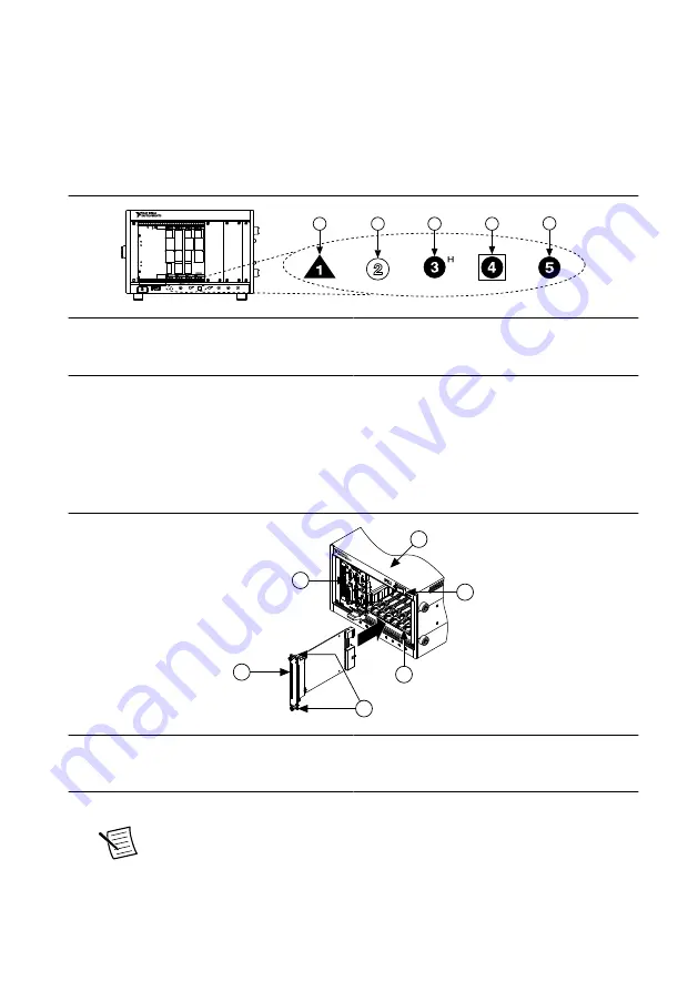
Identify a supported slot in the chassis. The following figure shows the symbols that
indicate the slot types.
Figure 2. Chassis Compatibility Symbols
NI PXIe-1062Q
1
2
3
4
5
1. PXI Express System Controller Slot
2. PXI Peripheral Slot
3. PXI Express Hybrid Peripheral Slot
4. PXI Express System Timing Slot
5. PXI Express Peripheral Slot
NI PXIe-7857R modules can be placed in PXI Express peripheral slots, PXI Express
hybrid peripheral slots, or PXI Express system timing slots.
6.
Touch any metal part of the chassis to discharge static electricity.
7.
Place the module edges into the module guides at the top and bottom of the chassis. Slide
the device into the slot until it is fully inserted.
Figure 3. Module Installation
PXI-1000B
1
2
3
4
5
6
1. Chassis
2. System Controller
3. Hardware Module
4. Front-Panel Mounting Screws
5. Module Guides
6. Power Switch
8.
Secure the device front panel to the chassis using the front-panel mounting screws.
Note
Tightening the top and bottom mounting screws increases mechanical
stability and also electrically connects the front panel to the chassis, which can
improve the signal quality and electromagnetic performance.
9.
Cover all empty slots with filler panels or use slot blockers to maximize cooling air flow.
4
|
ni.com
|
NI PXIe-7857R Getting Started Guide


