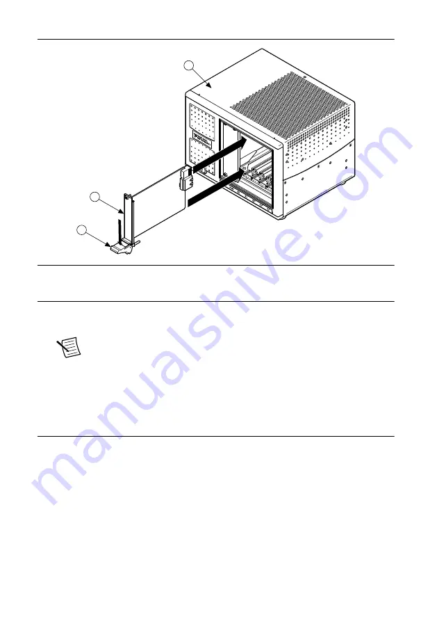
background image

Figure 3.

  Module Installation

2

3

1

1. Chassis
2. Hardware
3. Ejector Handle in Down (Unlatched) Position

9. Latch the module in place by pulling up on the ejector handle.
10. Secure the device front panel to the chassis using the front-panel mounting screws.

Note


Tightening the top and bottom mounting screws increases mechanical

stability and also electrically connects the front panel to the chassis, which can

improve the signal quality and electromagnetic performance.

11. Cover all empty slots using filler panels or slot blockers to maximize cooling air flow.
12. Power on the chassis.

Verifying Hardware Installation for Host Targets

You can verify that the system recognizes the NI PXIe-7820R by using Measurement &

Automation Explorer (MAX).
1. Launch MAX by navigating to 

Start

»

All Programs

»

National Instruments

»

MAX

 or by

clicking the MAX desktop icon.

2. Expand 

Devices and Interfaces

.

3. Verify that the device appears under 

Devices and Interfaces

.

If the device does not appear, press <F5> to refresh the view in MAX. If the device does

not appear after refreshing the view, visit 

ni.com/support

 for troubleshooting

information.

NI PXIe-7820R Getting Started Guide

  | 

© National Instruments

  | 

5

Summary of Contents for PXIe-7820

Page 1: ...PXIe 7820...

Page 2: ...a manner not specified in this user manual Product misuse can result in a hazard You can compromise the safety protection built into the product if the product is damaged in any way If the product is...

Page 3: ...orts and connected to the product using a shielded cable If unshielded cables or accessories are not properly installed and shielded the EMC specifications for the product are no longer guaranteed Cau...

Page 4: ...se only Note Refer to the device datasheet on ni com manuals for complete specifications Installing Software on the Host Computer Before using the NI PXIe 7820R you must install the following applicat...

Page 5: ...from all the captive screws on the module front panel 5 Identify a supported slot in the chassis The following figure shows the symbols that indicate the slot types Figure 2 Chassis Compatibility Sym...

Page 6: ...ts using filler panels or slot blockers to maximize cooling air flow 12 Power on the chassis Verifying Hardware Installation for Host Targets You can verify that the system recognizes the NI PXIe 7820...

Page 7: ...d Devices and Interfaces If the device does not appear press F5 to refresh the view in MAX If the device does not appear after refreshing the view visit ni com support for troubleshooting information...

Page 8: ...6 51 17 52 18 53 19 54 20 55 21 56 22 57 23 58 24 59 25 60 26 61 27 62 28 63 29 64 30 65 31 66 32 67 33 68 34 x is the connector number External Clock x is an input only DIO 0 31 Digital I O data thro...

Page 9: ...aximum voltage and current When the system powers on the DIO channels are set as input low with pull down resistors To set another power on state you can configure the NI PXIe 7820R to load a VI when...

Page 10: ...onger than 3 m 10 ft For each connected I O cable install two 2 snap on ferrite beads 777297 01 one on each end of the cable as close to the connector as practical Two 2 snap on ferrite beads 777297 0...

Page 11: ...l support At ni com support you have access to everything from troubleshooting and application development self help resources to email and phone assistance from NI Application Engineers National Inst...

Page 12: ...and third party legal notices in the readme file for your NI product Refer to the Export Compliance Information at ni com legal export compliance for the National Instruments global trade compliance p...

Reviews: