


38
|
ni.com
|
NI PXIe-5693 Calibration Procedure
34. Calculate the RF input power
using the following equation:
RF Input Power = Peak Amp Cable and 10 dB Attenuator Loss
35. Calculate the reverse isolation using the following equation:
Reverse Isolation = RF Output Power - RF Input Power
36. Repeat steps 27 through 35 for all remaining frequencies in Table 14.
37. Compare the calculated notch filter
reverse isolation values to the verification test limits in
Table 15.
38. Close the NI 5693 session.
If the reverse isolation verification procedure determines that the NI 5693 is outside of its limits,
refer to
Worldwide Support and Services
for information about support resources or service
requests.
Verifying Calibration Signal Amplitude Accuracy
1.
Connect the RF source 1 to the power splitter input using the SMA (m)-to-SMA (m) cable.
2.
Connect power sensor B to channel B on the power meter and to the reference output of the
power splitter.
3.
Connect the other output of the power splitter to the NI 5693 RF IN connector using the
SMA (m)-to-SMA (m) adapter.
4.
Connect power sensor A to channel A on the power meter and to the NI 5693 RF OUT
connector using the SMA (f)-to-SMA (m) semi-rigid cable and the 6 dB attenuator.
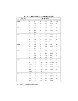
Table 15.
Reverse Isolation Verification Test Limits
Filter Path
NI 5693
Preamp
Enabled
NI 5693 Center
Frequency
As-Found
Limit (dB)
As-Left
Limit (dB)
Filters 1 to 4
Off
20 MHz to 160 MHz
39
43
On
39
43
Filters 5 to 8
Off
>160 MHz to
950 MHz
38
42
On
38
42
Filters 9 to 12
Off
>950 MHz to 3 GHz
35
38
On
35
38
Filters 13 to 16
Off
>3 GHz to 7 GHz
35
38
On
35
38
Notch Filter
Off
32 MHz to 166 MHz
35
37