


NI PXIe-5693 Calibration Procedure
|
© National Instruments
|
37
17. Measure the channel A power using the appropriate calibration factor for the power sensor
frequency.
18. Calculate the RF output power using the following equation:
RF Output Power = Channel A Power + Sensor/20 dB Attenuator/Splitter Tracking
19. Measure the peak amplitude using the spectrum analyzer.
20. Calculate the RF input power
using the following equation:
RF Input Power = Peak Amp Cable and 10 dB Attenuator Loss
21. Calculate the reverse isolation using the following equation:
Reverse Isolation = RF Input Power - RF Output Power
22. Repeat steps 12 through 21 for all remaining filters and frequencies in Table 13.
23. Repeat steps 12 through 21 for all filters and frequencies in Table 13 with the NI 5693
preamp enabled.
24. Compare the calculated reverse isolation for filters 1 through 16 to the verification test
limits in Table 15.
25. Disable the NI 5693 preamp.
26. Enable the NI 5693 notch filter path.
27. Set the NI 5693 center frequency according the first row in Table 14.
28. Commit the NI 5693 settings to hardware.
29. Set the spectrum analyzer center frequency according to the first row in Table 14.
30. Set the RF source 1 frequency according to the first row in Table 14.
31. Measure the channel A power using the appropriate calibration factor for the power sensor
frequency.
32. Calculate the RF output power using the following equation:
RF Output Power = Channel A Power + Sensor/20 dB Attenuator/Splitter Tracking
33. Measure the peak amplitude using the spectrum analyzer.
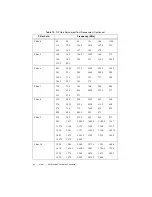
Table 14.
Reverse Isolation Test Frequencies for Notch Filter Path
Center Frequency (MHz)
Source Frequency (MHz)
35
4,647.5
70
4,682.5
100
4,712.5
130
4,742.5