background image

NI 5114 Calibration Procedure

|

© National Instruments

|

7

4.

Launch the Calibration dialog box by selecting 

Utility»Self Calibration

.

5.

Click 

OK

 to begin self-calibration.

NI-SCOPE

To self-calibrate the NI 5114 programmatically using NI-SCOPE, complete the following steps:
1.

Disconnect or disable any AC inputs to the device.

2.

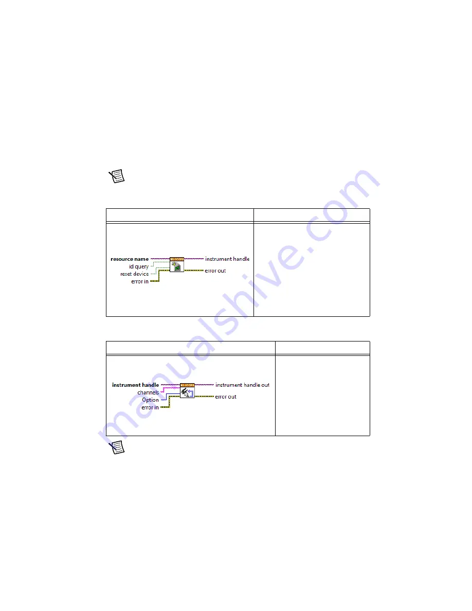
Open a session and obtain a session handle using the niScope Initialize VI.

Note

Throughout the procedure, refer to the C/C++ function call parameters for the 

LabVIEW input values.

3.

Self-calibrate the device using niScope Cal Self Calibrate VI.

Note

Because the session is a standard session rather than an external calibration 

session, the new calibration constants are immediately stored in the EEPROM. 
Therefore, you can include this procedure in any application that uses the device. 

LabVIEW VI

C/C++ Function Call

Call 

niScope_init

 with the 

following parameters:

vi

: The returned session handle that 

you use to identify the instrument in all 
subsequent NI-SCOPE driver function 
calls

resourceName

: The device name 

assigned by MAX

idQuery

VI_FALSE

resetDevice

:  

VI_TRUE


LabVIEW VI

C/C++ Function Call

Call 

niScope_CalSelf

Calibrate


with the 

following parameters:

sessionHandle

: The 

instrument handle from 

niScope_init

channelList

VI_NULL

option

VI_NULL

Summary of Contents for PXI

Page 1: ...libration 4 Self Calibration 4 Test Equipment 4 Calibration Procedures 5 Initial Setup 5 Test Conditions 5 Self Calibration 6 MAX 6 NI SCOPE Soft Front Panel 6 NI SCOPE 7 Verification 8 Vertical Offse...

Page 2: ...in the niScopeCal h file To use these constants in C you must include niScopeCal h in your code when you write the calibration procedure For more information on the calibration VIs and functions refer...

Page 3: ...ace IVI Drivers niScope Examples Directory of NI SCOPE examples for CVI C Visual C and Visual Basic NI High Speed Digitizers Getting Started Guide Contains NI SCOPE installation hardware installation...

Page 4: ...times a day may cause excessive wear on the relays over time Test Equipment Table 3 lists the equipment required for externally calibrating the NI 5114 If you do not have the recommended instruments u...

Page 5: ...Always connect the calibrator test head directly to the input BNC of the device or use a short 50 BNC coaxial cable if necessary Long cables and wires act as antennas picking up extra noise that can a...

Page 6: ...sed in another program MAX To initiate self calibration from MAX complete the following steps 1 Disconnect or disable any AC inputs to the device 2 Launch MAX 3 Select My System Devices and Interfaces...

Page 7: ...niScope Cal Self Calibrate VI Note Because the session is a standard session rather than an external calibration session the new calibration constants are immediately stored in the EEPROM Therefore y...

Page 8: ...y of the NI 5114 To verify vertical offset accuracy complete the procedures described in the Vertical Offset Accuracy section for each of the 20 iterations listed in Table 4 for channel 0 then repeat...

Page 9: ...4 8 125 10 9 125 20 10 125 40 11 20 0 04 12 20 0 1 13 20 0 2 14 20 0 4 15 20 1 16 20 2 17 20 4 18 20 10 19 20 20 20 20 40 Table 4 NI 5114 Input Parameters for Vertical Offset Accuracy and Vertical Ga...

Page 10: ...W input values 2 Configure the input impedance and the maximum input frequency using the niScope Configure Chan Characteristics VI LabVIEW VI C C Function Call Call niScope_init with the following par...

Page 11: ...abVIEW VI C C Function Call Call niScope_Configure Vertical with the following parameters coupling NISCOPE_VAL_DC probeAttenuation 1 0 vi The instrument handle from niScope_init channelList 0 range Th...

Page 12: ...n of the verification 10 Repeat steps 2 through 9 for each iteration in Table 4 11 Move the calibrator test head to device input channel 1 and repeat steps 2 through 10 for every configuration in Tabl...

Page 13: ...e Calibration Test Limits V Published Specifications V PXI PXIe PCI PXI PXIe PCI 0 04 0 00024 0 00032 0 00032 0 0004 0 1 0 0002 0 00048 0 0005 0 00058 0 2 0 0004 0 00068 0 0008 0 00088 0 4 0 0008 0 00...

Page 14: ...figureChan Characteristics with the following parameters channelList 0 inputImpedance NISCOPE_VAL_1_MEG_OHM maxInputFrequency The Maximum Input Frequency value in Table 4 for the current iteration Lab...

Page 15: ...impedance matching and frequency of the calibrator to settle 8 Initiate a waveform acquisition using the niScope Initiate Acquisition VI LabVIEW VI C C Function Call Call niScope_Configure HorizontalT...

Page 16: ...that corresponds to the vertical range used 11 Wait 2 500 ms for the impedance matching and frequency of the calibrator to settle 12 Initiate a waveform acquisition using the niScope Initiate Acquisi...

Page 17: ...ifications column listed in Table 6 If the result is within the selected test limit the device has passed this portion of the verification 15 Repeat steps 2 through 14 for each iteration in Table 5 16...

Page 18: ...Limits and Published Specifications Range V Positive Input V Negative Input V Calibration Test Limits Published Specifications 0 04 0 018 0 018 1 3975 1 5 0 1 0 045 0 045 1 3975 1 5 0 2 0 09 0 09 1 39...

Page 19: ...eristics with the following parameters vi The instrument handle from niScope_init channelList 0 inputImpedance NISCOPE_VAL_1_MEG_OHM maxInputFrequency 20 000 000 LabVIEW VI C C Function Call Call niSc...

Page 20: ...ching and frequency of the calibrator to settle 9 Initiate a waveform acquisition using the niScope Initiate Acquisition VI LabVIEW VI C C Function Call Call niScope_Configure HorizontalTiming with th...

Page 21: ...C Function Call Call niScope_FetchMeasurem ent with the following parameters timeout 1 0 vi The instrument handle from niScope_init channelList 0 scalarMeasFunction NISCOPE_VAL_VOLTAGE _AVERAGE LabVIE...

Page 22: ...the Measurement Scalar DBL instance of the VI This value is the Measured Negative Voltage used in step 17 17 Calculate the error in the programmable vertical offset as a percentage of input using the...

Page 23: ...ue of the channelList parameter from 0 to 1 20 End the session using the niScope Close VI LabVIEW VI C C Function Call Call niScope_close with the following parameter vi The instrument handle from niS...

Page 24: ...re Vertical VI LabVIEW VI C C Function Call Call niScope_init with the following parameters resourceName The device name assigned by MAX idQuery VI_FALSE resetDevice VI_TRUE LabVIEW VI C C Function Ca...

Page 25: ...dance matching and frequency of the calibrator to settle 8 Initiate a waveform acquisition using the niScope Initiate Acquisition VI LabVIEW VI C C Function Call Call niScope_Configure HorizontalTimin...

Page 26: ...million ppm using the following formula error a 11 000 000 11 where a is the measured frequency Compare the result to the Published Specifications column listed in Table 8 If the result is within the...

Page 27: ...h is optional 1 Open a session and obtain a session handle using the niScope Initialize VI LabVIEW VI C C Function Call Call niScope_close with the following parameter vi The instrument handle from ni...

Page 28: ...istics with the following parameters vi The instrument handle from niScope_init channelList 0 inputImpedance NISCOPE_VAL_50_OHM maxInputFrequency The Maximum Input Frequency value in Table 9 for the c...

Page 29: ...input impedance of the device 7 Wait 2 500 ms for the impedance matching and frequency of the calibrator to settle 8 Initiate a waveform acquisition using the niScope Initiate Acquisition VI LabVIEW V...

Page 30: ...l properties using the niScope Configure Horizontal Timing VI LabVIEW VI C C Function Call Call niScope_Fetch Measurement with the following parameters timeout 1 0 vi The instrument handle from niScop...

Page 31: ...Calculate the power difference using the following formula power 20log10 a 20log10 b where a is the Measured RMS Voltage of Generated Sine Wave b is the Measured RMS Voltage of 50 kHz Sine Wave If th...

Page 32: ...e entries for iterations 5 and 6 LabVIEW VI C C Function Call Call niScope_close with the following parameter vi The instrument handle from niScope_init Table 9 NI 5114 Bandwidth and Flatness Stimuli...

Page 33: ...t with the following parameters resourceName The device name assigned by MAX idQuery VI_FALSE resetDevice VI_TRUE LabVIEW VI C C Function Call Call niScope_ConfigureChan Characteristics with the follo...

Page 34: ...re HorizontalTiming with the following parameters enforceRealtime NISCOPE_VAL_TRUE numRecords 50 vi The instrument handle from niScope_init minSampleRate 250 000 000 refPosition 50 0 minNumPts 1 000 L...

Page 35: ...e 9 Initiate a waveform acquisition using the niScope Initiate Acquisition VI 10 Acquire a waveform using the niScope Fetch poly VI Select the Cluster instance of the VI LabVIEW VI C C Function Call C...

Page 36: ...the following changes Change channelList to 0 in steps 2 3 and 10 Connect the calibrator test head to the external trigger channel TRIG in step 7 14 End the session using the niScope Close VI LabVIEW...

Page 37: ...erform An adjustment is required only once every two years Following the adjustment procedure automatically updates the calibration date and temperature in the EEPROM of the device Complete all of the...

Page 38: ...rom 0 to 1 10 Using a BNC cable connect REF FREQUENCY OUTPUT on the back of the calibrator to the channel 0 input of the device Make sure the output of the reference frequency is enabled and set to 10...

Page 39: ...e niScope Cal End VI LabVIEW VI C C Function Call Call niScope_Cal AdjustVCXO with the following parameters sessionHandle The instrument handle from niScope_CalStart stimulusFreq 10 000 000 LabVIEW VI...

Page 40: ...ify the performance of the NI 5114 after adjustments Table 11 NI 5114 Input Parameters for External Adjustment Iteration Range V Input V 1 40 18 2 20 9 3 10 4 5 4 4 1 8 5 2 0 9 6 1 0 45 7 0 4 0 18 8 0...

Page 41: ...ts the device is guaranteed to meet or exceed its published specifications for a full calibration interval two years For this reason you must verify against the calibration test limits when performing...

Page 42: ...ogrammatically using NI SCOPE functions MAX To retrieve data using MAX complete the following steps 1 Select the device from which you want to retrieve information from My System Devices and Interface...

Page 43: ...ope_CalFetchDate niScope Cal Fetch Date VI niScope_CalFetchMiscInfo niScope Cal Fetch Misc Info VI niScope_CalFetchTemperature niScope Cal Fetch Temperature VI niScope_CalStoreMiscInfo niScope Cal Sto...

Reviews: