


NI PXI-8109 Installation Guide
2
ni.com
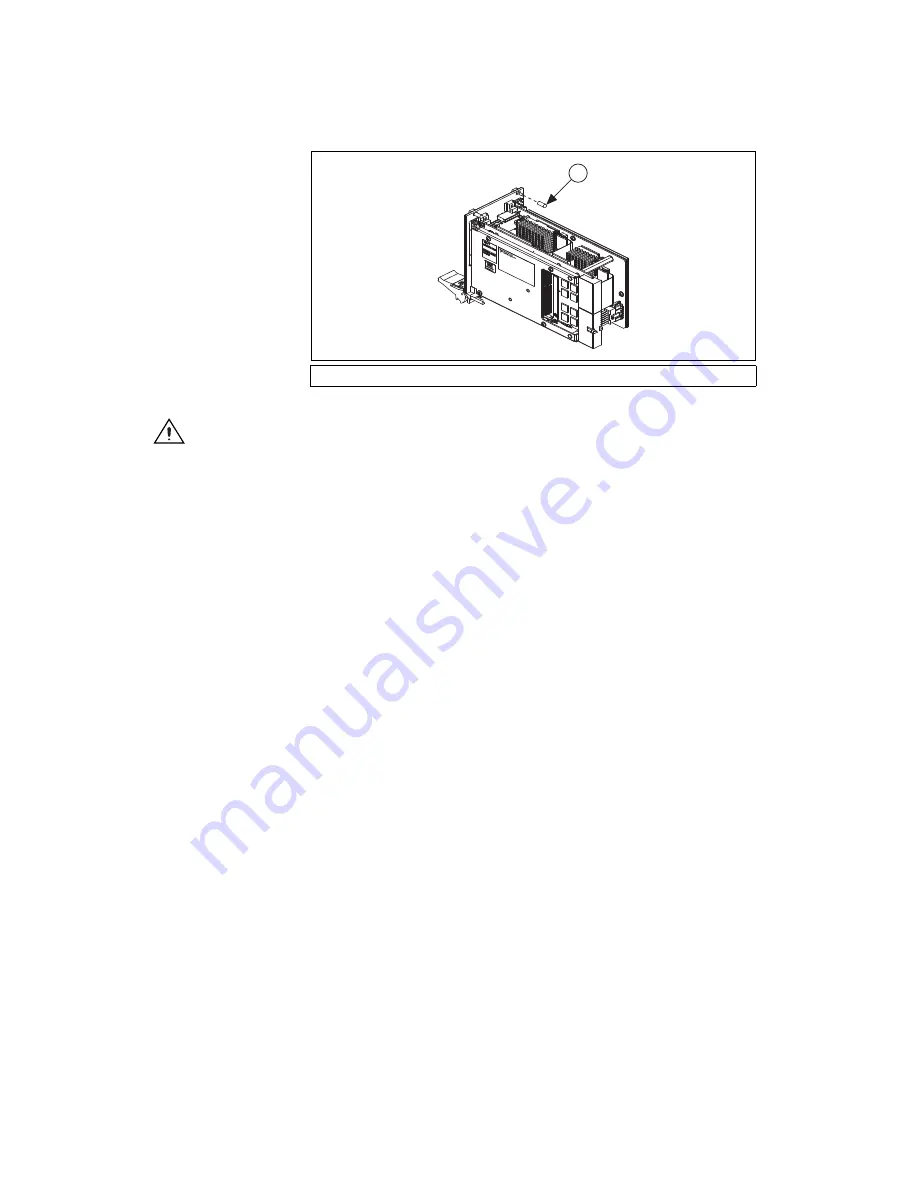
Figure 1.
Removing Protective Screw Caps
Caution
Do
not
raise the injector/ejector handle as you insert the NI PXI-8109. The
module will not insert properly unless the handle is in its downward position so that it does
not interfere with the injector rail on the chassis.
6.
Hold the handle as you slowly slide the module into the chassis until
the handle catches on the injector/ejector rail.
7.
Raise the injector/ejector handle until the module firmly seats into the
backplane receptacle connectors. The front panel of the NI PXI-8109
should be even with the front of the chassis.
8.
Tighten the four bracket-retaining screws on the top and bottom of the
front panel to secure the NI PXI-8109 to the chassis.
9.
Check the installation.
10. Connect the keyboard and mouse to the USB connectors. If you are
using a PS/2 keyboard and a PS/2 mouse, use USB-to-PS/2 adapters
to connect both to the USB connectors on the front panel. You may
use a Y-splitter adapter to connect both keyboard and mouse to one
USB port, leaving the other USB ports free for other peripherals, such
as a CD-ROM drive, or secondary hard drive. National Instruments
offers a Y-splitter adapter cable, part number 778713-02, available
through the online catalog at
ni.com/products
.
11. Connect the DVI monitor video cable to the DVI connector. If you are
using a VGA monitor, use the DVI-to-VGA adapter included with
your kit.
12. Connect peripherals to ports as required by your system configuration.
13. Power on the display. Refer to the
NI PXI-8109 User Manual
for
details.
14. Power on the chassis.
15. Verify that the controller boots. If it does not boot, refer to the
the NI PXI-8109 Does Not Boot?
section later in this guide.
1
Protective Screw Cap (4X)
1