background image

©

 National Instruments Corporation

5

Getting Started with the NI PCIe-8255R
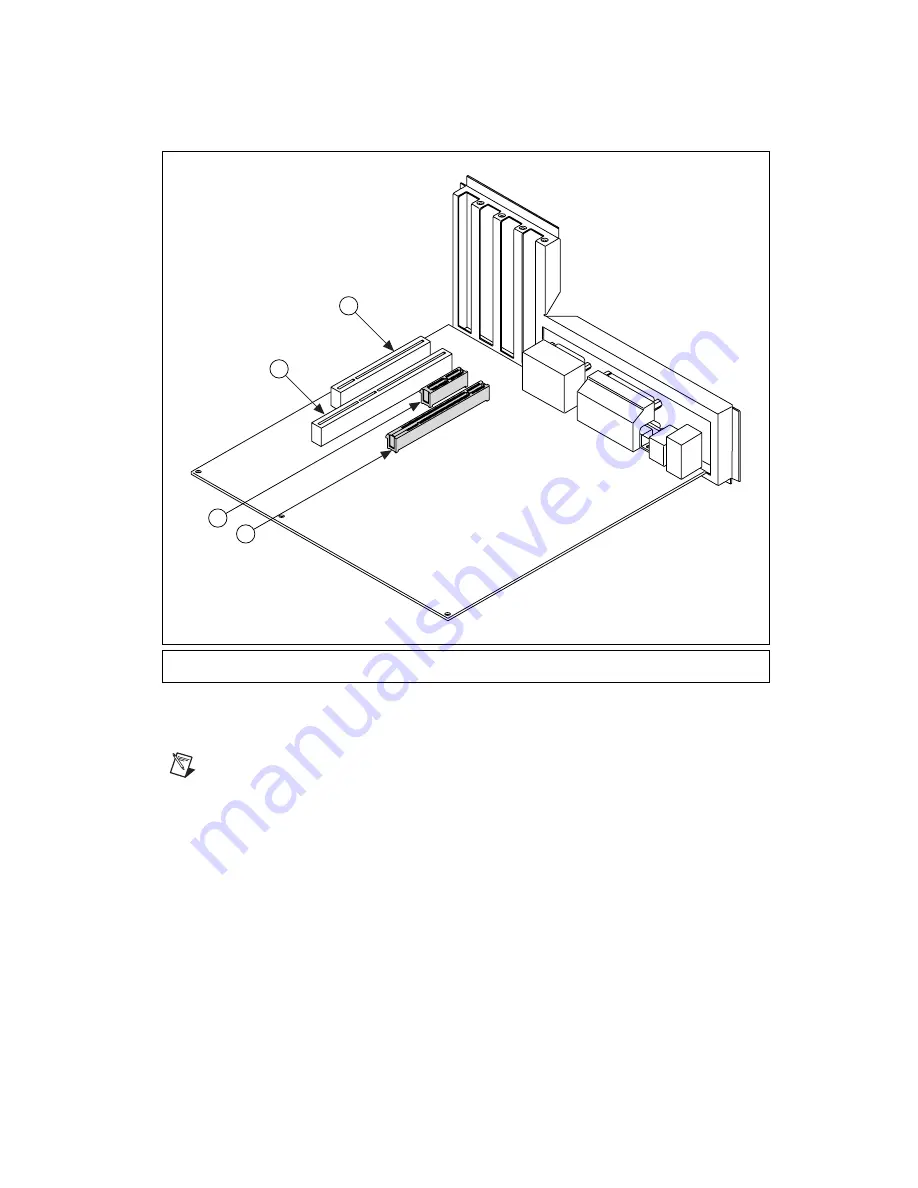
Figure 1.  

PC Expansion Slots

6.

Remove your device from the antistatic package and gently rock the NI 8255R into the slot. The 
connection may be tight, but do 

not

 force the device into place.

Note

Check that the bracket of your device aligns up with the hole in the back panel rail of the 

computer chassis.

7.

Secure the device mounting bracket to the back panel rail of the computer.

8.

To provide power to your camera, connect an unused power connector from the ATX power supply 
on your computer to the camera power ATX connector on your NI 8255R. Refer to Figure 2 for 
information about placement of the connectors on the NI 8255R.

1

PCI 32-bit Connector

2

PCI 64-bit and/or PCI-X Connector

3

PCIe x1 Connector

4

PCIe x16 Connector

2

1

3

4

Summary of Contents for NI PCIe-8255R

Page 1: ...and NI IMAQ I O driver software Optional software for developing applications NI Vision Development Module NI Vision Builder for Automated Inspection LabVIEW LabWindows CVI Microsoft Visual Basic Opti...

Page 2: ...esult in a hazard and may compromise the safety protection built into the device If the device is damaged turn it off and do not use it until service trained personnel can check its safety If necessar...

Page 3: ...to as MAINS4 voltage This category is for measurements of voltages from specially protected secondary circuits Such voltage measurements include signal levels special equipment limited energy parts o...

Page 4: ...s for the NI 8255R 1 Install NI Vision Acquisition Software before installing the NI 8255R Refer to the NI Vision Acquisition Software Release Notes for specific installation instructions 2 Power off...

Page 5: ...e aligns up with the hole in the back panel rail of the computer chassis 7 Secure the device mounting bracket to the back panel rail of the computer 8 To provide power to your camera connect an unused...

Page 6: ...plete the following steps to connect power for the isolated outputs to the NI 8255R Caution Do not connect the NI 8255R isolated power to a source less than 5 VDC or greater than 30 VDC Doing so could...

Page 7: ...If you are using the NI desktop power supply skip this step and proceed to step 3 a Wire the voltage output and the common mode ground output of the isolated power supply to one of the following optio...

Page 8: ...e when the computer is on and an isolated power supply is properly connected Configuring the NI 8255R After you have installed the NI 8255R and powered on the computer the computer will recognize the...

Page 9: ...ge 0 V to 5 V Maximum pulse rate 2 MHz Optically Isolated Inputs and Outputs Isolated Current Sinking Inputs Number of channels 13 Input voltage range 0 V to 30 V Input ON voltage 3 5 V to 30 V Input...

Page 10: ...6 in Weight 130 g 4 5 oz Environment The NI 8255R is intended for indoor use only Operating temperature 0 C to 55 C Storage temperature 20 C to 70 C Relative humidity 5 to 90 noncondensing Pollution D...

Page 11: ...ions Group 1 Class A CE C Tick ICES and FCC Part 15 Emissions Class A Note For EMC compliance operate this device according to product documentation CE Compliance This product meets the essential requ...

Page 12: ...ts calibration you can obtain the calibration certificate for your product at ni com calibration National Instruments corporate headquarters is located at 11500 North Mopac Expressway Austin Texas 787...

Reviews: