background image

8

|

ni.com

|

NI CVS-1458RT Getting Started Guide
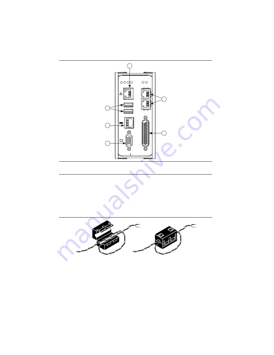
Figure 2.  

NI CVS-1458RT Front Panel Connectors

Connecting the System Power Supply

Complete the following steps to supply power to the NI CVS-1458RT.
1. Make sure the power source is turned off.
2. Install one ferrite across the negative and positive leads of the power source, approximately 

50 to 75 mm (2 to 3 in.) from the end of the power input wires, as shown in Figure 3.

Figure 3.  

Installing a Ferrite on the Power Leads

1

VGA Connector

2

RJ50 Serial Port

3

USB 2.0 Ports

4

RJ45 Network Port

5

Gigabit Ethernet PoE Ports

6

44-pin Digital I/O Connector

NI CVS-1458RT

Compact Vision System

RESET

DIGIT

AL I

/O

10/100/

1000

ACT/
LINK

USER1

USER2

PWR/

FA
U

L

T

ST
A

TUS

Po
E

0

P

oE POR

T 0

P

oE POR

T 1

Po
E

1

5

3

6

1

4

2

Summary of Contents for NI CVS-1458RT

Page 1: ...5 Installing the Vision Development Module 6 Configuring the Hardware 7 Connecting the System Power Supply 8 Connecting the Isolated Outputs Power Supply and PoE Power Supply 9 Connecting GigE Vision...

Page 2: ...1 000 Mbps CAT 5 cables are likely to cause bit errors resulting in degraded network performance Development computer running Microsoft Windows Refer to the driver or application development software...

Page 3: ...tion Software August 2014 One of the following options for developing machine vision applications NI Vision Builder for Automated Inspection Vision Builder AI 2014 or later LabVIEW 2014 or later LabVI...

Page 4: ...ation instructions All covers and filler panels must be installed while operating the device This is a Pollution Degree 2 device Do not operate the device in an explosive atmosphere or where flammable...

Page 5: ...y National Instruments could void your authority to operate it under your local regulatory rules Caution To ensure the specified EMC performance operate this product only with shielded cables and acce...

Page 6: ...ms National Instruments LabVIEW 4 NI Vision Development Module Refer to the NI Vision Development Module Readme on the NI Vision Development Module installation media for system requirements and insta...

Page 7: ...in or unplugging any connector Ground the unit to minimize the possibility of static electricity damage Complete the following sections to wire power to the NI CVS 1458RT connect cameras and connect t...

Page 8: ...egative and positive leads of the power source approximately 50 to 75 mm 2 to 3 in from the end of the power input wires as shown in Figure 3 Figure 3 Installing a Ferrite on the Power Leads 1 VGA Con...

Page 9: ...tor plug and tighten the terminal screw to 0 2 to 0 25 N m 1 8 to 2 2 lb in of torque 6 Install the power connector plug into the SYSTEM power receptacle on the NI CVS 1458RT chassis and tighten the c...

Page 10: ...torque 5 Connect the negative lead of the isolated outputs power source to the CISO terminal of the power connector plug and tighten the terminal screw to 0 2 to 0 25 N m 1 8 to 2 2 lb in of torque 6...

Page 11: ...to the development computer 1 Verify the that the development computer is powered on and connected to the network 2 Connect one end of an Ethernet cable to the network port on the device 3 Connect the...

Page 12: ...CVS 1458RT The default name for each device is NI CVS 1458RT XXXXXXXX where XXXXXXXX is the eight digit serial number 4 Right click Software and select Add Remove Software 5 Select NI IMAQdx NI Vision...

Page 13: ...ate and expand the NI CVS 1458RT The default name for each device is NI CVS 1458RT XXXXXXXX where XXXXXXXX is the eight digit serial number 4 Expand NI CVS 1458RT XXXXXXXX Devices and Interfaces 5 Sel...

Page 14: ...TTL 1 Bidirectional TTL I O 5 GND Digital ground reference for TTL and differential I O 6 TTL 2 Bidirectional TTL I O 7 TTL 3 Bidirectional TTL I O 8 GND Digital ground reference for TTL and differen...

Page 15: ...ral purpose isolated input 33 CISO Common ground reference for isolated inputs and outputs 34 Iso In 2 General purpose isolated input 35 Iso In 3 General purpose isolated input 36 CISO Common ground r...

Page 16: ...n Builder AI inspections are installed to the Vision Builder AI Examples directory where Vision Builder AI is the location Vision Builder AI is installed Additional Resources for LabVIEW Users Documen...

Page 17: ...ncil of the European Communities using the manufacturer s declaration of conformity This system affords the user protection for electromagnetic compatibility EMC and product safety You can obtain the...

Page 18: ...s You can find information about end user license agreements EULAs and third party legal notices in the readme file for your NI product Refer to the Export Compliance Information at ni com legal expor...

Reviews: