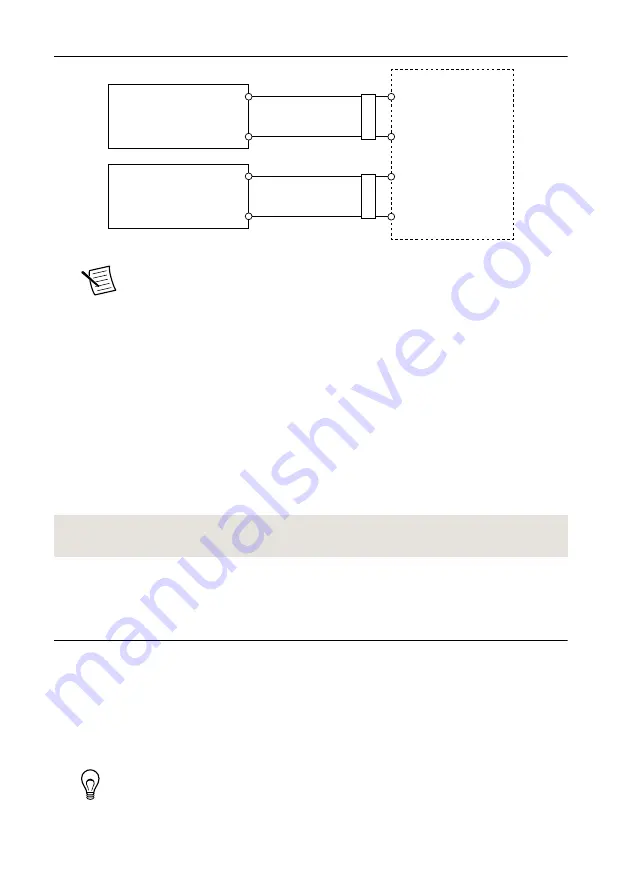
Figure 5.
cRIO-9024 Power Connections
Power Connector
V2
C
C
V1
Primary Power Supply
+
–
–
+
Secondary Power Supply
F
err
ite
F
err
ite
Note
The C terminals are internally connected to each other.
5.
Tighten the terminal screws on the power connector to 0.2 N · m to 0.25 N · m
(1.8 lb · in. to 2.2 lb · in.) of torque.
6.
Install the power connector on the front panel of the cRIO-9024.
7.
Tighten the power connector screw flanges to 0.3 N · m to 0.4 N · m (2.7 lb · in. to
3.5 lb · in.) of torque.
8.
Power on the primary power supply and optional secondary power supply.
Powering On the cRIO-9024
When you power on the cRIO-9024 for the first time, the device runs a power-on self test
(POST). During the POST, the Power and Status LEDs turn on. When the Status LED turns
off, the POST is complete.
Related Information
Configuring IP Settings and Installing Software
on the cRIO-9024
The cRIO-9024 initially boots into safe mode because there is no software installed. Complete
the following steps to configure the cRIO-9024 and install software.
1.
Launch MAX on the host computer.
2.
Expand
Remote Systems
in the configuration tree and locate your system.
3.
Select your target. MAX lists the system under the model number followed by the serial
number, such as NI-CRIO-9024-1856AAA.
Tip
If the cRIO-9024 is on a different subnet from the host computer, it does
not initially appear under Remote Systems. Use the CONSOLE OUT switch to
read the IP address of the cRIO-9024, and add it to Remote Systems in MAX.
NI cRIO-9024 User Manual and Specifications
|
© National Instruments
|
7


