3-12
|
ni.com
Chapter 3
Signal Connections
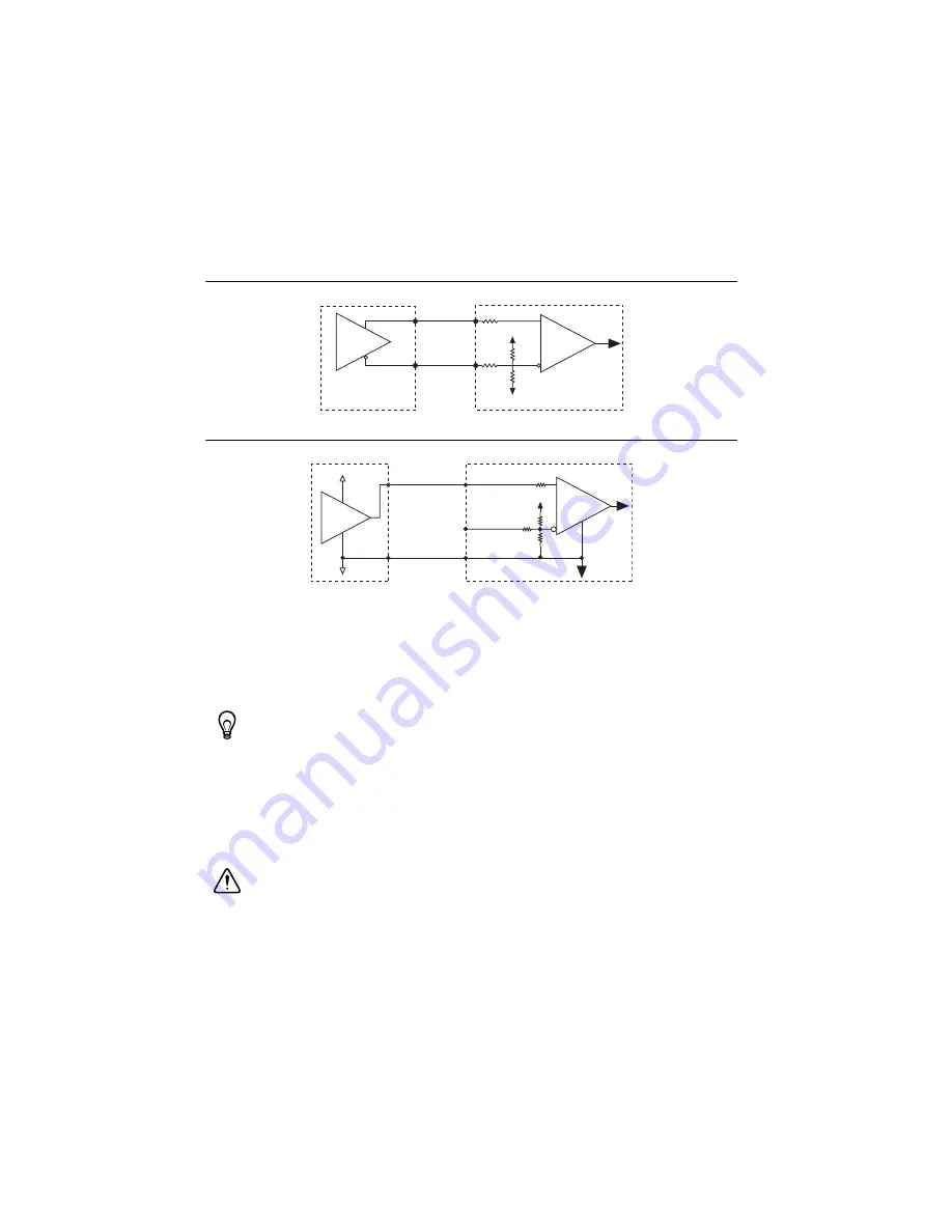
Figures 3-11 and 3-12 show simplified schematic diagrams of the encoder input circuit
connected to differential and single-ended inputs.
Figure 3-11.
Differential Encoder Input Circuit
Figure 3-12.
Single-Ended Encoder Input Circuit
Position Capture Input and Position Compare Output
The NI 951x drive interface modules have a high-speed Position Capture input and Position
Compare output. These signals are useful for high-speed synchronization of motion with
actuators, sensors, vision and data acquisition devices, and other components in the complete
motion system.
Tip
Refer to the
Signal Connection Recommendations
Accessory and Cable Connections
, for wiring and cabling recommendations.
•
Position Capture
—When enabled, an active transition on a high-speed Position Capture
input causes instantaneous position capture of the corresponding encoder count value. You
can use this high-speed position capture functionality for applications ranging from simple
logging of feedback sensor data to complex camming systems with advance/retard
positioning and registration.
Caution
If you use an open collector driver for the Position Capture input, provide
the voltage equivalent of a logical high during the off state of the open collector
driver. A common method to achieve this is by adding a pull-up resistor to the output.
Refer to the
section of Appendix A,
, for information about
the Position Capture input voltage levels.
Receiver
Ph
as
e +
Ph
as
e –
Encoder
NI 951x
+5 V
COM
Receiver
Ph
as
e+
Encoder
NI 951x
No
Connection
Ph
as
e–
+5 V
COM
+5 V
COM


