background image

NI 9467 Operating Instructions and Specifications

10

ni.com

For example, if yo

u


u

se an active antenna with gain of 28 dB and 

RG-58 cable, which has a rated loss at 1.5 GHz of abo

u

t 0.8 dB/m 

(24.5 dB/100 ft), the maxim

u

m cable length yo

u

 co

u

ld 

u

se is:

Max_cable_loss = –130 dBm + 28 dB – (–125 dBm) = 23 dB

Max_cable_length = 23 dB / (0.8 dB/m) 

 29 m

Sleep Mode

This mod

u

le s

u

pports a low-power sleep mode. S

u

pport for sleep 

mode at the system level depends on the chassis that the mod

u

le is 

pl

u

gged into. Refer to the chassis man

u

al for information abo

u

s

u

pport for sleep mode. If the chassis s

u

pports sleep mode, refer to 

the software help for information abo

u

t enabling sleep mode. Visit 

ni.com/info

 and enter 

c

s

erie

s

doc

 for information abo

u

C Series doc

u

mentation.

Typically, when a system is in sleep mode, yo

u

 cannot 

comm

u

nicate with the mod

u

les. In sleep mode, the system 

cons

u

mes minimal power and may dissipate less heat than it does 

in normal mode. Refer to the 

Specifications

 section for more 

information abo

u

t power cons

u

mption and thermal dissipation.

Summary of Contents for NI 9467

Page 1: ...OPERATING INSTRUCTIONS AND SPECIFICATIONS NI 9467 C Series GPS Synchronization Module ni com manuals Deutsch Français ...

Page 2: ...this document are specific to the NI 9467 The other components in the system might not meet the same safety ratings and specifications Refer to the documentation for each component in the system to determine the safety ratings and specifications for the entire system Visit ni com info and enter cseriesdoc for information about C Series documentation Safety Guidelines Caution Do not operate the NI ...

Page 3: ...llow these guidelines if you are installing the NI 9467 in a potentially explosive environment Not following these guidelines may result in serious injury or death Caution Do not disconnect I O side wires or connectors unless power has been switched off or the area is known to be nonhazardous Caution Do not remove modules unless power has been switched off or the area is known to be nonhazardous C...

Page 4: ... or Ex nL IIC T4 equipment Electromagnetic Compatibility Guidelines This product was tested and complies with the regulatory requirements and limits for electromagnetic compatibility EMC stated in the product specifications These requirements and limits provide reasonable protection against harmful interference when the product is operated in the intended operational electromagnetic environment Th...

Page 5: ... specified EMC performance operate this product only with shielded cables and accessories Special Conditions for Marine Applications Some products are Lloyd s Register LR Type Approved for marine shipboard applications To verify Lloyd s Register certification for a product visit ni com certification and search for the LR certificate or look for the Lloyd s Register mark on the product label Cautio...

Page 6: ... At start up the NI 9467 automatically begins determining its location through a process known as self survey During the self survey the module computes a location fix every second and averages the locations at the end to obtain a more accurate location After the self survey the NI 9467 no longer computes new location fixes it uses its known location and satellite signals to generate accurate timi...

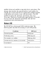
Page 7: ...ellites broadcast the ephemeris and almanac data every 30 seconds Therefore it usually takes approximately 30 seconds for it to receive the ephemeris and almanac data and start computing location and timing fixes Status LED The NI 9467 has a front panel LED to indicate status The following table describes the meaning of each LED pattern Conditions LED state Normal operation Solid green Performing ...

Page 8: ...ls Connecting the NI 9467 The NI 9467 has one SMA female connector on its front panel for a GPS active antenna The connector provides a DC voltage to power the antenna and also serves as input for the GPS RF signal Antenna Installation Caution National Instruments recommends using a lightning arrester in line with the GPS antenna installation to protect the NI 9467 and the C Series system from pos...

Page 9: ...deline is that the GPS antenna should have a straight line of sight to the sky in all directions 360 down to an imaginary line making a 30 angle with the ground Locations far from trees and tall buildings that could block or reflect GPS satellite signals are best Maximum Cable Length Maximum cable length depends on the GPS antenna gain and the cable s loss per unit of distance National Instruments...

Page 10: ...tem level depends on the chassis that the module is plugged into Refer to the chassis manual for information about support for sleep mode If the chassis supports sleep mode refer to the software help for information about enabling sleep mode Visit ni com info and enter cseriesdoc for information about C Series documentation Typically when a system is in sleep mode you cannot communicate with the m...

Page 11: ...satellites When the module exits sleep mode and power to the GPS receiver is restored the module goes through the normal power up process which includes the ephemeris almanac data acquisition and self survey process Therefore it can take approximately 30 seconds before usable timing and location signaling can be generated Refer to Start Up Behavior for more information ...

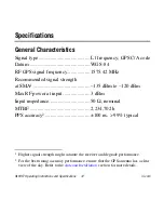
Page 12: ...mmended signal strength at SMA1 135 dBm to 120 dBm Max RF power at input 3 dBm Input impedance 50 Ω nominal MTBF 2 234 702 h PPS accuracy2 100 ns 99 typical 1 Higher signal strength might saturate the receiver and degrade performance 2 For the best timing accuracy performance ensure that the GPS antenna has a clear view of the sky Refer to the Antenna Installation section for more details ...

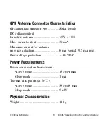
Page 13: ...tage output for active antenna 5 V 10 Max current output 30 mA Minimum current for antenna presence detection 6 mA typical 9 5 mA max Over voltage protection 30 VDC Power Requirements Power consumption from chassis Active mode 150 mA max Sleep mode 1 mA Thermal dissipation at 70 C Active mode 550 mW max Sleep mode 5 mW Physical Characteristics Weight 141 g ...

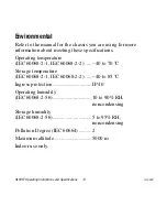
Page 14: ...ting these specifications Operating temperature IEC 60068 2 1 IEC 60068 2 2 40 to 70 C Storage temperature IEC 60068 2 1 IEC 60068 2 2 40 to 85 C Ingress protection IP 40 Operating humidity IEC 60068 2 56 10 to 90 RH noncondensing Storage humidity IEC 60068 2 56 5 to 95 RH noncondensing Pollution Degree IEC 60664 2 Maximum altitude 5000 m Indoor use only ...

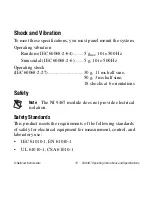
Page 15: ...Hz Sinusoidal IEC 60068 2 6 5 g 10 to 500 Hz Operating shock IEC 60068 2 27 30 g 11 ms half sine 50 g 3 ms half sine 18 shocks at 6 orientations Safety Note The NI 9467 module does not provide electrical isolation Safety Standards This product meets the requirements of the following standards of safety for electrical equipment for measurement control and laboratory use IEC 61010 1 EN 61010 1 UL 61...

Page 16: ...2 Groups A B C D T4 Class I Zone 2 AEx nA IIC T4 Canada C UL Class I Division 2 Groups A B C D T4 Class I Zone 2 Ex nA IIC T4 Europe DEMKO Ex nA IIC T4 Electromagnetic Compatibility This product meets the requirements of the following EMC standards for electrical equipment for measurement control and laboratory use EN 61326 1 IEC 61326 1 Class A emissions Industrial immunity EN 55011 CISPR 11 Grou...

Page 17: ...l and heavy industrial locations In Europe Canada Australia and New Zealand per CISPR 11 Class A equipment is intended for use only in heavy industrial locations Note Group 1 equipment per CISPR 11 is any industrial scientific or medical equipment that does not intentionally generate radio frequency energy for the treatment of material or inspection analysis purposes Note For EMC declarations and ...

Page 18: ...laration of Conformity DoC for additional regulatory compliance information To obtain product certifications and the DoC for this product visit ni com certification search by model number or product line and click the appropriate link in the Certification column Environmental Management NI is committed to designing and manufacturing products in an environmentally responsible manner NI recognizes t...

Page 19: ...l and Electronic Equipment WEEE EU Customers At the end of the product life cycle all products must be sent to a WEEE recycling center For more information about WEEE recycling centers National Instruments WEEE initiatives and compliance with WEEE Directive 2002 96 EC on Waste and Electronic Equipment visit ni com environment weee ᄤֵᙃѻક ᶧ ࠊㅵ ࡲ Ё RoHS Ё ᅶ National Instruments ヺড়Ё ᄤֵᙃ ѻકЁ䰤ࠊՓ ᶤѯ ᆇ 䋼ᣛ...

Page 20: ...mpliance policy and how to obtain relevant HTS codes ECCNs and other import export data Where to Go for Support The National Instruments Web site is your complete resource for technical support At ni com support you have access to everything from troubleshooting and application development self help resources to email and phone assistance from NI Application Engineers National Instruments corporat...

Reviews: