National Instruments NI 9157 Operating Instructions And Specifications Download Page 15

©

 National Instruments Corporation

15

NI 9157/9159 Operating Instructions and Specifications

Powering Down the MXI-Express System

Always power down the host system before powering down any connected 
NI 9157/9159 chassis. When the host system is powered down, the order in 
which connected NI 9157/9159 chassis are powered down is not important.

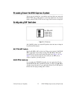
Configuring DIP Switches
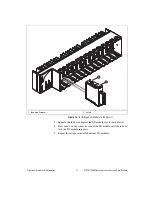
Figure 13.  

DIP Switches

All of the DIP switches are in the OFF position when the chassis is shipped 
from National Instruments.
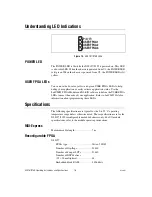
NO FPGA APP Switch

Push the NO FPGA APP switch to the ON position to prevent a LabVIEW 
FPGA application from loading at startup. The NO FPGA APP switch 
overrides the chassis powerup options described in the 

Chassis Powerup 

Options

 section. After startup you can download to the FPGA from 

software regardless of switch position.

USER FPGA Switches

You can define the USER FPGA switches for your application. Use the 
LabVIEW FPGA Module and NI-RIO software to define the USER FPGA 
switches to meet the needs of your application. Refer to 

LabVIEW Help

 for 

information about programming these switches.

NO FPGA APP
USER FPGA1
USER FPGA2
USER FPGA3

OFF

Summary of Contents for NI 9157

Page 1: ...r chassis and how to use the features of the NI 9157 9159 This document also contains specifications for the NI 9157 9159 1 LEDs 2 Upstream Port 3 MXI Express LINK LEDs 4 Downstream Port 5 Power Conne...

Page 2: ...l the system in an enclosure rated to at least IP 54 as defined by IEC 60529 and EN 60529 Special Conditions for Hazardous Locations Use in Europe Some chassis have been evaluated as Ex nA IIC T4 equi...

Page 3: ...ay not be compatible with systems using noncompliant clocks particularly clocks with peak frequencies higher than 100 MHz For more information about PCI Express clock compatibility with the NI 9157 91...

Page 4: ...mbient temperature at each side of the chassis 63 5 mm 2 5 in from the side and 50 8 mm 2 in forward from the rear of the chassis as shown in Figure 3 Note For more information about how different mou...

Page 5: ...ith Dimensions 1 Measure ambient temperature here 63 5 mm 2 50 in 50 8 mm 2 in 406 3 mm 16 in 50 8 mm 2 in 48 4 mm 1 91 in 1 1 89 4 mm 3 52 in 63 5 mm 2 50 in 29 mm 1 14 in Cabling Clearance 50 8 mm 2...

Page 6: ...ail mount kit if you want to mount the chassis on a DIN rail You need one clip for mounting the chassis on a standard 35 mm DIN rail Complete the following steps to mount the chassis on a DIN rail 1 F...

Page 7: ...on the NI 9157 9159 2 Insert one edge of the DIN rail into the deeper opening of the DIN rail clip as shown in Figure 7 Figure 7 One Edge of the DIN Rail Inserted in a Clip 3 Press down firmly on the...

Page 8: ...ns You can use the NI 9907 panel mount kit to mount the NI 9157 9159 on a flat surface Complete the following steps 1 Fasten the panel mounting plate to the chassis using a number 2 Phillips screwdriv...

Page 9: ...e the NI 9907 panel mount kit and do not require the portability that the NI 9907 affords you can mount the NI 9157 9159 directly on a flat surface using the three mounting holes Complete the followin...

Page 10: ...mensions Complete the following steps to install a C Series I O module in the chassis 1 Make sure that no I O side power is connected to the I O module If the system is in a nonhazardous location the...

Page 11: ...2 Installing an I O Module in the Chassis 3 Squeeze the latches and insert the I O module into the module slot 4 Press firmly on the connector side of the I O module until the latches lock the I O mod...

Page 12: ...s one layer of reverse voltage protection Complete the following steps to connect a power supply to the chassis 1 Connect the positive lead of the power supply to the V1 or V2 terminal of the COMBICON...

Page 13: ...Use a MXI Express cable to connect the MXI Express host system to the Upstream port of the first NI 9157 9159 in the chain 5 Use a MXI Express cable to connect the Downstream port of the first NI 915...

Page 14: ...for Status After powering on the chassis and host system check the MXI Express LINK LEDs to ensure that all connected systems are linked and communicating properly The MXI Express LINK LEDs of the NI...

Page 15: ...om National Instruments NO FPGA APP Switch Push the NO FPGA APP switch to the ON position to prevent a LabVIEW FPGA application from loading at startup The NO FPGA APP switch overrides the chassis pow...

Page 16: ...IO software to define the USER FPGA LEDs to meet the needs of your application Refer to LabVIEW Help for information about programming these LEDs Specifications The following specifications are typica...

Page 17: ...ce requirements for the country of use Recommended power supply 55 W 30 VDC max Voltage requirement 9 to 30 V Chassis power consumption dissipation NI 9157 With no I O modules 14 4 W max With 14 I O m...

Page 18: ...ure IEC 60068 2 1 and IEC 60068 2 2 0 C to 55 C Note Refer to the mounting instructions in the Mounting the NI 9157 9159 section of this document Failure to follow the mounting instructions in that se...

Page 19: ...ectrical distribution system referred to as MAINS voltage MAINS is a hazardous live electrical supply system that powers equipment This category is for measurements of voltages from specially protecte...

Page 20: ...mitted to designing and manufacturing products in an environmentally responsible manner NI recognizes that eliminating certain hazardous substances from our products is beneficial to the environment a...

Page 21: ...tside the Untied States contact your local branch office Australia 1800 300 800 Austria 43 662 457990 0 Belgium 32 0 2 757 0020 Brazil 55 11 3262 3599 Canada 800 433 3488 China 86 21 5050 9800 Czech R...

Page 22: ...struments trademarks Other product and company names mentioned herein are trademarks or trade names of their respective companies For patents covering National Instruments products technology refer to...

Reviews: