background image

Verify the System IP Configuration

1.

Put the NI 9147 in safe mode by holding the RESET button down for 5 seconds.

The STATUS LED starts blinking three times every few seconds.

2.

Set a new DHCP connection by holding the RESET button down for 5 seconds. The
STATUS LED repeats the same behavior from 

Step 1

.

If the NI 9147 fails to set a new DHCP address, it assigns itself a link-local IP address. If
the DHCP connection is successful and appropriate for your application, skip to 

Step 5

.

3.

In MAX, expand your system under Remote Systems.

4.

Select the 

Network Settings

 tab to configure the IP and other network settings.

5.

Reboot the NI 9147 by pressing the RESET button.

Configure the Windows Firewall

Add an exception for MAX to your network firewall or other security software by
completing the following steps:
1.

On Windows 7, select 

Start

»

Control Panel

»

System and Security

»

Windows

Firewall

»

Allow a program through Windows Firewall

.

2.

Click 

Allow another program

.

3.

Select 

Measurement & Automation

.

4.

Click 

Add

.

5.

Click 

OK

.

Ensure that UDP port 44525 is open to communication on the host computer. If you are
using an intelligent switch on the network, ensure that it is not disabling UDP port 44525.
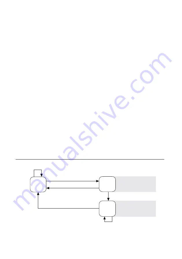
System Reset

The following figure shows the reset behavior of the NI 9147.

Figure 4.

 Reset Button Behavior

Press and hold RESET button for 

 5 s 

Press and hold RESET button for 

<

 5 s

Run Mode

Safe Mode

Press and hold RESET button for 

<

 5 s

Press and hold RESET button for 

 5 s

Press and hold

RESET button for 

 5 s 

Press and hold

RESET button for < 5 s 

• Network settings reset
• FPGA Startup App disabled

• FPGA Startup App disabled

Safe Mode

NI 9147 Getting Started Guide

  | 

© National Instruments

  | 

11

Summary of Contents for NI 9147

Page 1: ...ines for Hazardous Locations The NI 9147 is suitable for use in Class I Division 2 Groups A B C D T4 hazardous locations Class I Zone 2 AEx nA IIC T4 and Ex nA IIC T4 hazardous locations and nonhazard...

Page 2: ...Caution The system shall only be used in an area of not more than Pollution Degree 2 as defined in IEC 60664 1 Caution The system shall be mounted in an ATEX IECEx certified enclosure with a minimum i...

Page 3: ...designing selecting and installing measurement probes and cables to ensure that the desired EMC performance is attained Preparing the Environment Ensure that the environment in which you are using th...

Page 4: ...on the Host Computer Before using the NI 9147 you must install the following application software and device drivers on the host computer in this order 1 LabVIEW 2014 SP1 or later 2 LabVIEW FPGA Modu...

Page 5: ...dule with a slot and seat it in the slot until the latches lock in place Removing C Series Modules Verify that power is not connected to the I O connector s on the C Series module before you remove a...

Page 6: ...or larger Screwdriver Phillips 2 What to Do Complete the following steps to ground the NI 9147 1 Attach the ring lug to the wire 2 Remove the grounding screw from the grounding terminal on the NI 914...

Page 7: ...lists the POWER LED indicators Table 1 POWER LED Indicators LED Color LED Pattern Indication Green Solid The NI 9147 is powered on and the connected power supply is adequate Off The NI 9147 is powere...

Page 8: ...teps to connect the NI 9147 to the host computer using the USB device port 1 Power on the host computer 2 Connect the NI 9147 to the host computer using the USB A to B cable Caution NI requires the us...

Page 9: ...itoring prompts you to do so 2 Enter a unique name for your system in the Hostname field 3 Click the Security Configuration icon 4 Click Login 5 In the Login dialog box enter the username admin and le...

Page 10: ...mat of 172 22 11 x 2 In MAX expand your system under Remote Systems 3 Select the Network Settings tab to configure the IP and other network settings 4 Optional Use the RJ 45 Ethernet port 1 to reconne...

Page 11: ...k firewall or other security software by completing the following steps 1 On Windows 7 select Start Control Panel System and Security Windows Firewall Allow a program through Windows Firewall 2 Click...

Page 12: ...safe mode or the NI 9147 is in install mode to indicate that software is currently being installed This pattern may also indicate that the user has forced the NI 9147 to boot into safe mode by pressin...

Page 13: ...pplication Engineers Visit ni com services for NI Factory Installation Services repairs extended warranty and other services Visit ni com register to register your NI product Product registration faci...

Page 14: ...nts txt file on your media or the National Instruments Patent Notice at ni com patents You can find information about end user license agreements EULAs and third party legal notices in the readme file...

Reviews: