Chapter 4
Analog Input
©
National Instruments Corporation
4-15
With this type of connection, the PGIA rejects both the common-mode
noise in the signal and the ground potential difference between the signal
source and the device ground, shown as V
cm
in the figure. Refer to the
NI 6232/6233 Specifications
for the usable range of V
cm
.
Common-Mode Signal Rejection Considerations
For signal sources that are already referenced to some ground point with
respect to the device, the PGIA can reject any voltage caused by ground
potential differences between the signal source and the device. In addition,
with DIFF input connections, the PGIA can reject common-mode noise
pickup in the leads connecting the signal sources to the device. The PGIA
can reject common-mode signals as long as AI+ and AI– (input signals) are
both within ±11 V of AI GND.
Differential Input Biasing
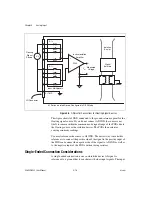
Figure 4-4 shows AI GND connected to the negative lead of the signal
source. If you do not connect AI GND, the source is not likely to remain
within the common-mode signal range of the PGIA due to the floating
source or the isolation barrier. The PGIA then saturates, causing erroneous
readings.
You must reference the source to AI GND. The easiest way to make this
reference is to connect the positive side of the signal to the positive input of
the PGIA and connect the negative side of the signal to AI GND as well as
to the negative input of the PGIA, without using resistors.
Differential Connections for Non-Referenced or Floating Signal Sources
Figure 4-5 shows how to connect a floating signal source to a channel
configured in DIFF mode.

