©
National Instruments Corporation
31
NI RF Signal Generators Getting Started Guide
6.
Navigate to the NI-RFSG VIs on the
Functions»Measurement I/O»
NI-RFSG
palette.
7.
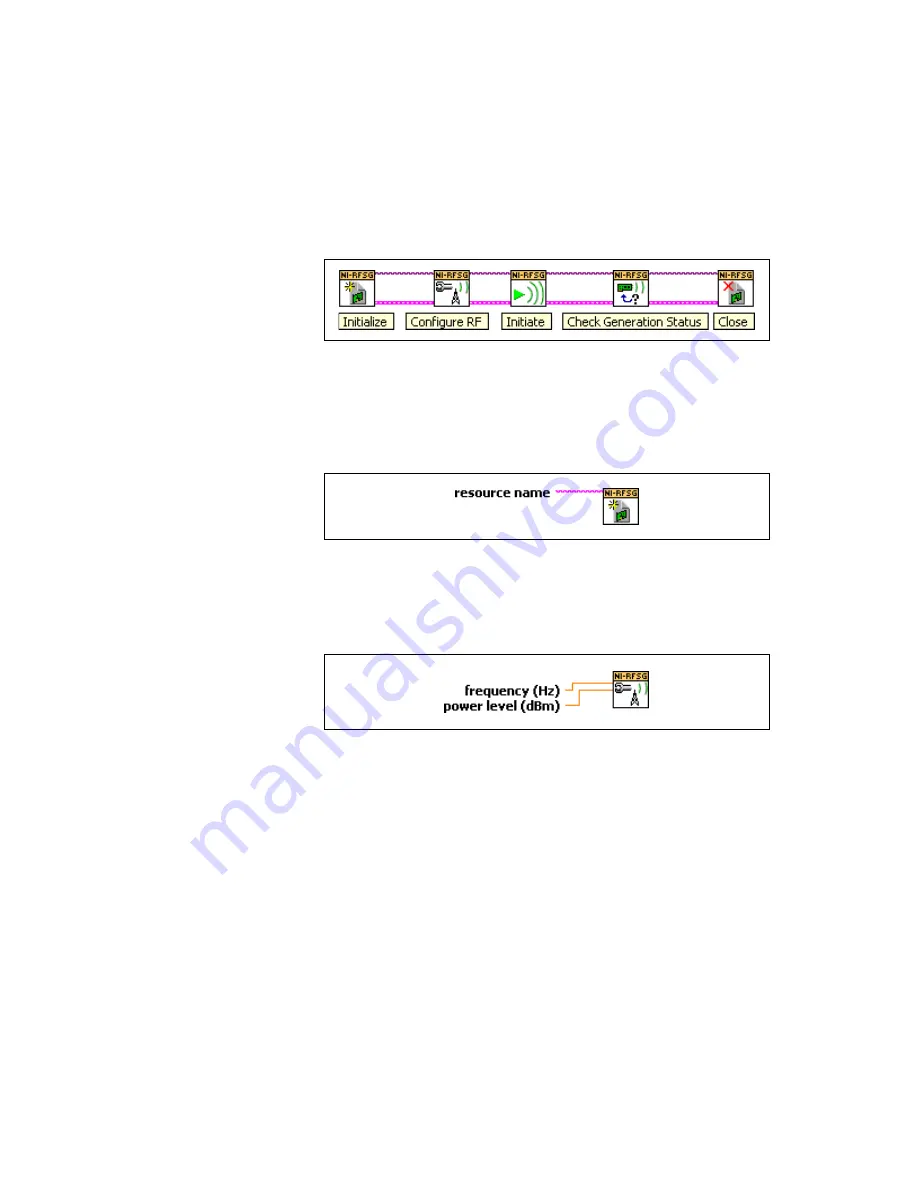
Create the block diagram shown in Figure 12 by wiring the five VIs on
the block diagram in the order in which they appear in the top row of
the NI-RFSG palette.
Figure 12.
Basic NI-RFSG Block Diagram
8.
Hover the cursor over the
resource name
terminal on the niRFSG
Initialize VI and right-click. Select
Create»Control
to create a front
panel control where you specify the NI RF signal generator device
name. The
resource name
terminal is shown in Figure 13.
Figure 13.
Resource Name Terminal on niRFSG Initialize VI
9.
Hover the mouse tool over the
frequency (Hz)
and
power level (dBm)
terminals of the niRFSG Configure RF VI.
These terminals are shown in Figure 14.
Figure 14.
Frequency and Power Level Terminals on the niRFSG Configure RF VI
10. Right-click each terminal and select
Create»Control
from the
shortcut menu to create frequency and power controls as shown
in Figure 15.