Chapter 5
Signal Connections
5-8
www.natinst.com
A typical encoder with a specification of N (N = number) lines per unit of
measure (revolutions or linear distance) produces 4
×
N quadrature counts
per unit of measure.
The count is the basic increment of position in
FlexMotion systems.
Note
Determine quadrature counts by multiplying the encoder resolution in encoder lines
by 4. The encoder resolution is the number of encoder lines between consecutive encoder
indexes (marker or Z-bit). If the encoder does not have an index output, the resolution
would be referred to as lines per revolution, or lines per unit of measure (inch, centimeter,
millimeter, and so on).
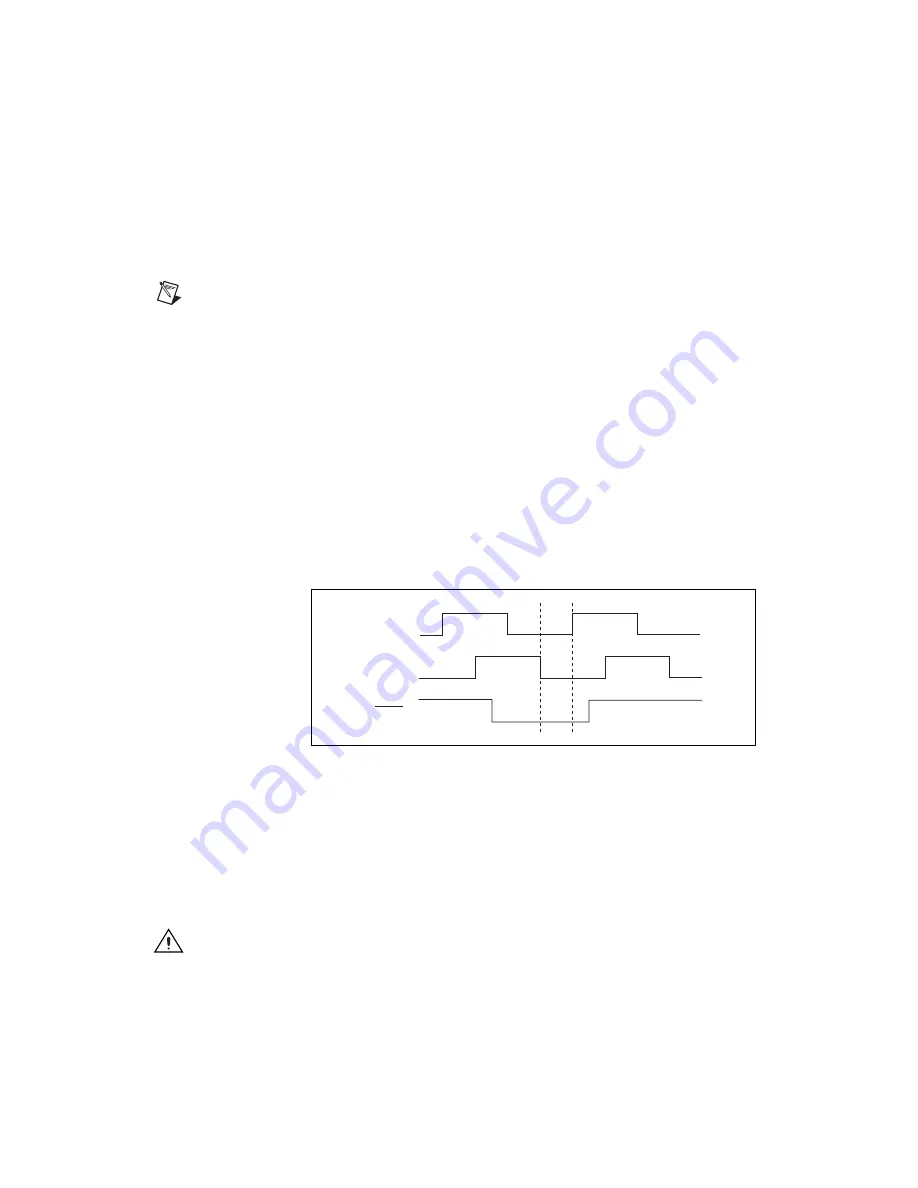
Encoder <1..4> Index
The Index input is primarily used with the Find Index function. This
function uses the number of counts per revolution (or linear distance) to
initiate a search move that locates the index position. When a valid Index
signal transition occurs during a Find Index sequence, the position of the
Index signal is captured very accurately. You then use this captured
position to establish a reference zero position for absolute position control
or any other motion system position reference required. Figure 5-3 shows
the quadrature encoder phasing diagram.
Figure 5-3.
Quadrature Encoder Phasing Diagram
Wiring Concerns
The encoder inputs are connected to quadrature decoder/counter circuits. It
is very important to minimize noise at this interface. Excessive noise on
these encoder input signals may result in loss of counts or extra counts and
erroneous closed-loop motion operation. Verify the encoder connections
before powering up the system.
Caution
Wire encoder signals and their ground connections separately from all other
connections. Wiring these signals near the motor drive/amplifier or other signals can cause
positioning errors and faulty operation.
Phase A
Phase B
Index


