Appendix H
Parallel Polling
©
National Instruments Corporation
H-3
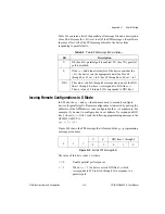
Table H-1 contains a list of the parallel poll message bits and a description
of each bit. Because the
U
bit is set in all of the PPD messages, they all have
the same effect. All of the PPD messages disable the device from
responding to parallel polls.
Issuing Remote Configurations in S Mode
In S Mode, the
ppc
and
ppu
functions are used to remotely configure
devices for parallel polls. Remote configuration is indicated by passing the
addresses of the GPIB devices to be configured in the
addr
arguments. For
example, if you want to configure a device at address 5 to respond on DIO
line 3 when its
ist
bit is 1, send the following programming message to the
GPIB-232/485CT-A:
ppc 5,3,1<CR>
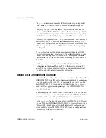
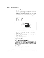
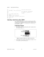
Figure H-2 shows the PPE message that is formed by the
ppc
programming
message given above.
Figure H-2.
Sample PPE Message Bits
The value of this byte is hex 6A where:
U
= 0
Enable parallel poll responses
S
= 1
When
ist
= 1 the device asserts DIO line 3 (which
corresponds to 010 in bits 0 through 2) in response to a
parallel poll.
Table H-1.
Parallel Poll Message Bit Descriptions
Bit
Description
U
If 0 (hex 6X), parallel poll is enabled. If 1 (hex 7X), parallel
poll is disabled.
S
If the
ist
(individual status) bit of the device matches the
S
bit, the device sets the appropriate data line. Hex 60
through hex 67, set
S
to 0; hex 68 through hex 6F, set
S
to 1.
DIO
The value
n
in bits 0 through 2 corresponds to one of the DIO
lines 1 through 8, where
n
corresponds to DIO line
n+1
.
Thus, a value of 2 (binary 010) corresponds to DIO line 3.
0
1
1
U
S
DIO lines 1 through 8
0
1
0
1
0


