Chapter 4
Arb Operation
©
National Instruments Corporation
4-7
DAQArb 5411 User Manual
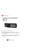
Figure 4-5.
Waveform Staging Block Diagram
Each stage is made up of four instructions:
•
Buffer number—Specifies the buffer number to be generated.
•
Buffer size—Specifies the total count of the buffer to be generated.
This count may be more or less than the actual size of that buffer.
If the count is less, only a part of that buffer will be used for that
stage. If the count is more than the actual size of that buffer, part of
the next sequential buffer will also be used. If the buffer size is set
to zero, the software will automatically use the true size of that
buffer.
•
Buffer loops—Specifies the number of times that buffer has to be
looped. The maximum number of loops possible is 65,535.
•
Marker offset—Specifies where the marker has to be generated
within that buffer. For more information on markers, see the
Markers section later in this chapter.
Note:
The maximum number of waveform stages the instruction FIFO can store
for Arb mode is 290.
Note:
For more information on the waveform generation process, refer to your
software manuals.
Figure 4-6 shows a simple case of waveform generation process.
80 MHz Oscillator
Div/2
16-Bit
Counter
Memory
Controller
Waveform Memory
Sequencer
+
Address Generator
Address
Buffer Number
Buffer Size
Marker Offset
Instruction FIFO
Data In (16)
Data Out (16)
Instructions
Buffer Loops