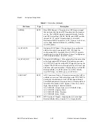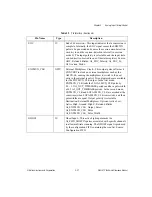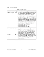
Chapter 2
Analog Input Timing/Control
©
National Instruments Corporation
2-11
DAQ-STC Technical Reference Manual
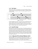
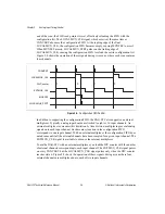
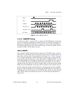
Figure 2-7.
External CONVERT Timing
Although successive CONVERT pulses in Figure 2-7 are equidistant, they could follow any
other timing.
2.4.2 Scan-Level Timing and Control
As discussed in section
, sequences of CONVERT pulses are organized
into scans. Each scan begins with a START pulse. The START pulse may come from either
the SI counter (internal START mode) or the PFI selector (external START mode).
2.4.2.1 Internal START Mode
In the internal START mode, the SI_TC (SI counter TC) signal becomes the START pulse.
The START1 trigger causes the SI counter to generate the START pulses which continue until
the acquisition sequence is complete. Refer to section
2.4.3, Acquisition-Level Timing and
, for more information on the START1 trigger.
The SI counter has dual-load registers that allow for two timing parameters at the START
timing level. The first parameter (A) gives the delay from START1 to the first START. The
second parameter (B) gives the delay between START pulses.
STOP
STST_GATE
SCAN_IN_PROG
CONVERT
START
External CONVERT


