Chapter 2
Analog Input Timing/Control
DAQ-STC Technical Reference Manual
2-4
©
National Instruments Corporation
2.3 Simplified Model
The AITM contains the hardware necessary to generate timing and control signals for the
ADC and the associated circuitry on a National Instruments DAQ board, such as an MIO
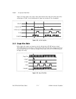
board. Figure 2-1 shows the timing and control signals used in a typical analog input
operation.
Figure 2-1.
Typical Analog Input Waveform
The primary analog input timing signal is the CONVERT pulse, which instructs the ADC to
begin a conversion on the selected analog input channel. CONVERT pulses are organized into
groups called scans. In each scan, the CONVERT signal pulses once for each input channel.
The purpose of the scan grouping is to sample multiple input channels nearly simultaneously.
Each scan begins with a START pulse and ends with a STOP pulse. The START1 trigger
begins the acquisition sequence. Figure 2-1 above depicts an acquisition consisting of three
scans, with each scan sampling four input channels.
START1
START
STOP
CONVERT

