Chapter 3
Analog Output Timing/Control
©
National Instruments Corporation
3-13
DAQ-STC Technical Reference Manual
using software interrupts. This section discusses the buffer timing modes available with the
DAQ-STC.
3.4.5.1 Single-Buffer Mode
In the single-buffer mode, the DAQ-STC provides UPDATE timing for one MISB. Software
programs the UC counter with the number of points in the buffer and programs the BC counter
with the number of buffer repetitions. The START1 trigger initiates the analog output.
Single-buffer mode analog output can be retriggerable or nonretriggerable. In the
retriggerable single-buffer mode, additional START1 pulses will initiate additional analog
output operations. In the nonretriggerable single-buffer mode, only one analog output
operation is allowed and the final UPDATE pulse in the MISB is masked. Therefore, you need
to add an extra UPDATE pulse to the first buffer in the nonretriggerable single-buffer mode.
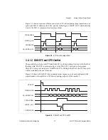
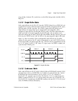
Figure 3-11 shows an example of the nonretriggerable single-buffer mode. The buffer
contains five data points, so the UC counter is programmed to count six UPDATE pulses in
the following buffers. The buffer is repeated twice, so the BC counter is programmed to count
two UC_TC pulses. The BC_TC (BC counter TC) signal causes the MISB to terminate and
masks the final UPDATE pulse.
Figure 3-11.
Single-Buffer Mode
3.4.5.2 Continuous Mode
In the single-buffer mode, the BC counter indicates when an MISB should terminate. In the
continuous mode, however, the MISB does not terminate at a predetermined time. Instead,
the MISB continues until the hardware receives an End_On_UC_TC command, an
End_On_BC_TC command, or an AO_Reset. The End_On_UC_TC command causes the
MISB to terminate at the next UC_TC, corresponding to the end of the current buffer. The
End_On_BC_TC command causes the MISB to terminate at the next BC_TC. The AO_Reset
causes the MISB to terminate immediately.
UPDATE
UC_TC
BC_TC
Iteration 1
Iteration 2
START1


