Chapter 3
Analog Output Timing/Control
©
National Instruments Corporation
3-7
DAQ-STC Technical Reference Manual
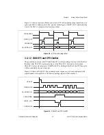
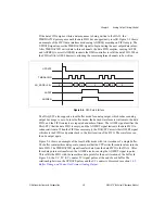
Figure 3-3 shows a sequence of three consecutive CPU-driven analog output operations, one
each to the DAC at addresses four, five, and six. In this figure, CHRDY_OUT is held until the
write to the DAC is complete (slow interface mode).
Figure 3-3.
CPU-Driven Analog Output
3.4.1.3 DAQ-STC and CPU Conflict
The possibility exists that the CPU and DAQ-STC will both attempt to write to the DACs at
the same time. The CPU is given priority over the DAQ-STC, but it can not interrupt a
DAQ-STC write cycle in progress. If the DAQ-STC is writing to the DACs, the CPU bus cycle
will be extended to the next write slot.
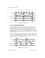
Figure 3-4 shows a DAQ-STC-driven analog output sequence on a board configured with
eight channels, interrupted by a CPU-driven analog output to DAC number 9.
Figure 3-4.
DAQ-STC and CPU Conflict
CPUDACREQ
CHRDY_OUT
CPUDACWR
AO_ADDR<3..0>
4
6
5
CPUDACREQ
CHRDY_OUT
CPUDACWR
AO_ADDR<3..0>
UPDATE
TMRDACWR
0
1
4
9
2
5
3
6
0
7

