Chapter 2
Analog Input Timing/Control
©
National Instruments Corporation
2-121
DAQ-STC Technical Reference Manual
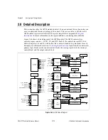
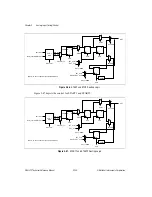
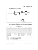
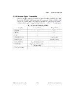
Figure 2-48 depicts the control for EXT_GATE.
Figure 2-48.
EXT_GATE Routing Logic
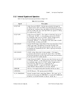
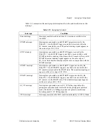
Table 2-10 summarizes the selections available for each of the trigger signals through the PFI
selector.
Table 2-10.
PFI Selectors
MUX
0
1–10
11–17
18
19
31
AI_START1_Source
SW
PFI<0..9>
RTSI<0..6>
GOUT0
—
GND
AI_START2_Source
SW
PFI<0..9>
RTSI<0..6>
—
—
GND
AI_SI_Source
AI_TB1
PFI<0..9>
RTSI<0..6>
—
TB2
GND
AI_CONVERT_Source
SI2_TC
PFI<0..9>
RTSI<0..6>
—
GOUT0
GND
AI_START_Source
SI_TC
PFI<0..9>
RTSI<0..6>
SW
GOUT0
GND
AI_STOP_Source
DIV_TC, SW
PFI<0..9>
RTSI<0..6>
SI2_TC
AI_STP
GND
AI_External_Gate
—
PFI<0..9>
RTSI<0..6>
—
—
GND
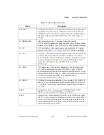
Key:
AI_STP
The input AI_STOP_IN
AI_TB1
The internal analog input signal AI_IN_TIMEBASE1
GOUT0
The G_OUT signal from general-purpose counter 0
SW
Software strobe
TB2
The internal signal IN_TIMEBASE2
PFI<0..9>
RTSI_TRIGGER<0..6>
MOUT
MOUT*
POLARITY
20 to 1
MUX
SEL<0..4>
NOTE: Does not show all possible selections.
OUT
EXT_TIMING
SC_CLK*
EXT_CLK
D
Q
R
SCAN_IN_PROG*


