Chapter 2
Analog Input Timing/Control
DAQ-STC Technical Reference Manual
2-112
©
National Instruments Corporation
2.8 Detailed Description
This section describes the AITM module in detail. You need not read this section unless you
need to understand the inner workings of the circuit. This section refers to bitfields in the
AITM-related registers in the DAQ-STC register map. Refer to Appendix B,
, for more information on the register addresses containing these bitfields.
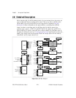
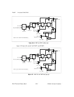
Figure 2-46 shows a block diagram of the AITM module. The AITM contains four
special-purpose counters—SI, SI2, SC, and DIV. Each of the counters (except DIV) has
dual-load registers (A and B), which allow the counters to handle two parameters for each
timing layer, as discussed in section
. Apart from the counters, the
primary logic blocks are the counter control blocks, the routing logic block, the interrupt
control block, and the output control block.
Figure 2-45.
AITM Block Diagram
AI_IN_TIMEBASE1
IN_TIMEBASE2
PFI<0..9>
CONVERT
SC_TC
LOCALMUX_CLK
EXTMUX_CLK
SCAN_IN_PROG
SOC
EOC
START1
START2
SC_SRC
START
STOP
SI_SRC
SCLK
RTSI_TRIGGER<0..6>
START1
START
STOP
SI_TC
SC_TC
SI_SRC
START1
STOP
DIV_TC
SC_TC
SC_SRC
START1
START2
STOP
SC_TC
SC_SRC
START1
START
STOP
SI2_TC
SC_TC
SI_SRC
AIFIFOREQ
AIERROR
SC_TC
START1
START2
START
STOP
SI_TC
SI2_TC
DIV_TC
SC Control
Logic
MODE
DIV
Control
Logic
SI
Control
Logic
MODE
SI2
Control
Logic
Output
Control
Routing
Logic
Interrupt
Control
Trg/Src SEL
SI2 Load A
SI2 Load B
SI Load A
SI Load B
DIV Load A
SC Load A
SC Load B
MUX
SC Counter
SC Save
DIV Counter
MUX
SI Counter
SI Save
MUX
SI2 Counter
SI_HOLD
SI2_CLK
SI2_LOAD
SI2_CE
SI2_LOAD_SRC
SI_CLK
SI_LOAD
SI_CE
SI_LOAD_SRC
DIV_CLK
DIV_LOAD
DIV_CE
SC_LOAD
SC_CE
SC_LOAD_SRC
SC_GATE
SC_HOLD
SC_CLK
SC_TC
DIV_TC
SI_TC
SI2_TC


