Chapter 2
Analog Input Timing/Control
DAQ-STC Technical Reference Manual
2-6
©
National Instruments Corporation
FIFO flags AIFEF (AI data FIFO empty flag), AIFHF (AI data FIFO half-full flag), and
AIFFF (AI data FIFO full flag). Refer to section
, for a complete
description of these signals.
The configuration FIFO may also supply the GHOST signal, which is updated on every
CONVERT. When the GHOST input is active, the AI_FIFO_SHIFTIN pulse is suppressed
following the conversion, so that the ADC data is not shifted into the AI data FIFO. This
feature allows the DAQ-STC to support multirate sampling where channels are sampled at
different input rates.
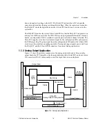
As shown in Figure 2-2, the START pulse may come from the SI counter (internal START
source) or the PFI selector (external START source). Similarly, the STOP pulse may come
from the DIV counter (internal STOP source) or the PFI selector (external STOP source). The
SCAN_IN_PROG output indicates that a scan is in progress by asserting on START and
deasserting on STOP.
The SC counter is available to count the number of scans that have occurred. This is useful
for generating a specific number of scans in an acquisition. The START1 trigger signal begins
the acquisition sequence and may come from one of several sources—PFI, RTSI, software, or
general-purpose counter 0.
2.4 Analog Input Functions
The AITM is a highly flexible circuit that can accommodate a variety of timing scenarios. The
most useful of these is the interval scanning mode. For this reason, the functional description
will present interval scanning as the primary analog input mode.
For the purpose of discussion, the analog input functions can be divided into three
groups—low-level timing and control, scan-level timing and control, and acquisition-level
timing and control. Low-level timing and control refers to the timing signals related to and
derived from CONVERT. Scan-level timing and control refers to the timing signals necessary
to organize the CONVERT pulses into scans. Acquisition-level timing and control refers to
the timing signals that govern the generation of scan sequences.
2.4.1 Low-Level Timing and Control
This section discusses CONVERT and the signals derived from CONVERT.
The CONVERT signal is the primary timing signal for analog input. Three board-level
subsystems are controlled by CONVERT and the signals derived from CONVERT—the
ADC, the data FIFO, and the configuration FIFO and external multiplexer. CONVERT timing
is affected by your selection of internal or external CONVERT mode.

