Chapter 2
Analog Input Timing/Control
©
National Instruments Corporation
2-107
DAQ-STC Technical Reference Manual
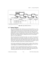
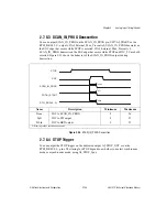
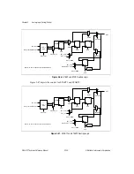
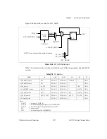
The numbers in parentheses are the actual numbers to load into the on-chip counters to
achieve the desired delay.
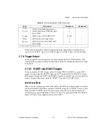
Table 2-8 shows the minimum number of clock periods that must occur between related
signals in order for their recognition to be valid. Notice that this does not take into account
the setup or synchronization time for the external signals, as covered in section
. The External Control column is applicable when the signal is originating outside
the DAQ-STC. The DAQ-STC minimum and maximum columns apply to the internally
generated signals.
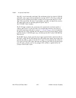
The START1 trigger is the only trigger in the posttrigger mode and is the first trigger in the
pretrigger mode. It triggers the acquisition sequence and can be generated by software or by
an external pulse (refer to AI_START1_Select). The software trigger, which is caused by
setting AI_START1 to 1, generates the correct pulsewidth automatically. The external pulse
must meet the latch and recognition-time parameters that are indicated in section
, for its selected mode of operation.
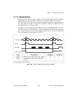
The START trigger enables a particular scan and is generated by either an external signal or
the internal signal SI_TC (refer to AI_START_Select). The SI counter is started by the
START1 trigger and can be programmed to count anywhere from 2 to 2
24
clock periods. The
external signal must meet the setup and pulsewidth requirements indicated in section
, in order to guarantee recognition by the AITM.
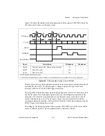
The CONVERT output signal causes an actual conversion to occur and can be caused either
by an external signal or the internal signal SI2_TC, inverted (refer to
AI_CONVERT_Source_Select). The SI2 counter is started by the START trigger and can be
programmed to count anywhere from 2 to 2
16
clock periods. The external signal must meet
the setup and pulsewidth requirements that are indicated in section
,
in order to guarantee recognition by the AITM. The external signal can be passed through the
Table 2-8.
Interval Scanning Mode Timing
Name
Description
External
Control
Minimum in
Clock Periods
Maximum in
Clock Periods
Tst1st
START1 to START
0
1 (1)
2
24
-
1 (2
24
-1)
Tstst
START to START
2
2 (1)
2
24
-1 (2
24
-1)
Tstc
START to CONVERT
0
1 (1)
2
24
-1 (2
24
-1)
Tcc
CONVERT to CONVERT
2
2 (1)
2
16
(2
16
-1)
Tstpc
STOP to CONVERT
0
0
—
Tstpst
STOP to START
0
0
—
Ttcst2
SC_TC to START2
1
1
—
Tst2stp
START2 to STOP
1
1 (1)
2
24
-
1 (2
24
-1)

