Chapter 2
Analog Input Timing/Control
©
National Instruments Corporation
2-99
DAQ-STC Technical Reference Manual
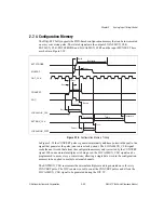
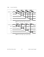
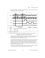
Figure 2-30.
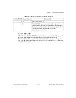
START2 Delays, Synchronous Mode, External CONVERT
Asynchronous Mode
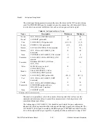
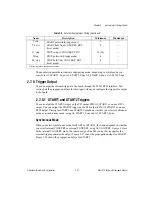
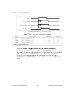
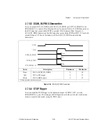
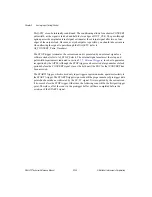
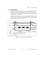
When you select asynchronous mode for START1 or START2, the external trigger itself
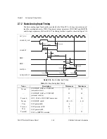
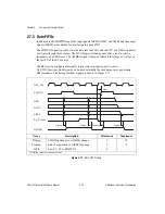
generates the rising edge of the output. Figure 2-31 shows the propagation delays for
START1. Figure 2-32 shows the propagation delays for START2.
Figure 2-31.
START1 Delays, Asynchronous Mode
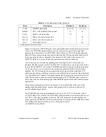
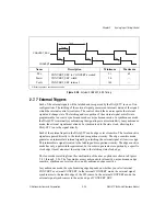
Table 2-6.
START1 and START2 Timing, Synchronous Mode
Name
Description
Minimum
Maximum
Tpfi
Source to PFI output
10
41
Trtsi
Source to RTSI output
12
46
Tbrd
Source to BRD output
18
63
All timing values are in nanoseconds.
START2
CONVERT_SRC
PFI1/AI_START2
RTSI_TRIGGER<0..6>
RTSI_BRD<0..3>
Tpfi
Trtsi
Tbrd
START1
PFI0/AI_START1
RTSI_TRIGGER<0..6>
RTSI_BRD<0..3>
Tpfi
Trtsi
Tbrd

