Chapter 1
Introduction
PCI-4451/4452/4453/4454 User Manual
1-6
www.ni.com
♦
PCI-4453/4454
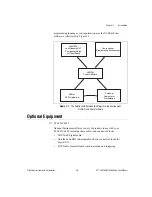
National Instruments offers optional products to use with your
PCI-4453/4454, including these cables and connector blocks:
•
SMB-to-BNC cable for external trigger
•
RTSI cable for multiboard synchronization and triggering
Custom Cabling
National Instruments offers different types of cables in varying lengths, and
the BNC-214X DSA accessories to connect your analog I/O to a PCI-445X
device. National Instruments also offers cables of different lengths and
accessories to connect your digital I/O signals to the PCI-4451/4452.
National Instruments recommends you do not develop your own cabling
solution due to the difficulty of working with the high-density connector
and the need to maintain high signal integrity. If your application requires
that you develop your own cable, follow the guidelines in this section.
Analog Cables
National Instruments recommends using the SHC68-DB25 cable for those
applications that require custom accessories. The SHC68-DB25 cable, a
shielded 68-position VHDCI connector cabled to a standard DB-25 shell,
facilitates the creation of custom termination solutions.
♦
PCI-4451/4452
Use shielded twisted-pair wires for each differential analog input or output
channel pair. Since the signals are differential, using this type of wire yields
the best results.
When connecting the cable shields, be sure to connect the analog input
grounds to the AIGND pins and the analog output grounds to the AOGND
pins. For connector pin connections and assignments, refer to Figure 4-1,
Analog Pin Connections for the PCI-4451/4452
and to Table 4-1,
I/O Connector Pin Assignment for the PCI-4451/4452
♦
PCI-4453/4454
When connecting the cable shields, be sure to connect the analog input
grounds to the AI_SHLDx pins and the analog output grounds to the
AO_SHLDx pins. For connector pin connections and assignments, refer to
Figure 4-2,
Analog Pin Connections for the PCI-4453/4454
and to
Table 4-3,


