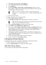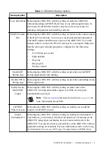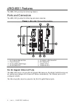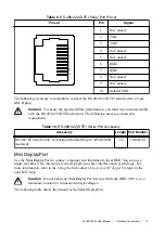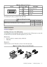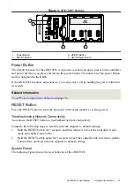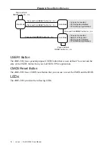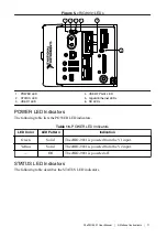
Figure 5. cRIO-9031 LEDs
5
4
1
2
3
6
1. POWER LED
2. STATUS LED
3. USER1 LED
4. USER FPGA1 LED
5. Gigabit Ethernet LEDs
6. SD LEDs
POWER LED Indicators
The following table lists the POWER LED indicators.
Table 16. POWER LED Indicators
LED Color
LED Pattern
Indication
Green
Solid
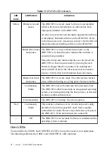
The cRIO-9031 is powered from the V1 input.
Yellow
Solid
The cRIO-9031 is powered from the V2 input.
—
Off
The cRIO-9031 is powered off.
STATUS LED Indicators
The following table describes the STATUS LED indicators.
NI cRIO-9031 User Manual
|
© National Instruments
|
17


