background image

Components and Assembly

7

LOADING AND UNLOADING

•  Always disconnect from power source before transporting. 
•  Ensure blanks are installed in magnetic tooling pockets during transport. 
•  Loosen handle securing bolt to slide handle down for loading/unloading. Re-tighten 

the bolts when handle is at the desired height.

HANDLE ASSEMBLY

Handle adjusts in both height and angle. To make adjustments, complete the following:

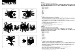
1.  Loosen the handle bolt and adjust the handle to the desired length (Figure 1); re-

tighten bolt.  

2.  Adjust handle grip to desired angle and firmly secure (Figure 1.1).  
3.  Adjust handle to desired angle and secure with clip and support pin (Figure 1.2).

VACUUM PORT 

The machine has a dust collection port located at the rear (Figure 2A). Use a dust col-

lection hose that snugly fits either on the outside or the inside of the port. The dual short 

hose connection runs from the grinder deck to the ‘Y’ splitter (Figure 2B).

RUBBER DUST GUARD

Attaching

1.  Ensure machine is in upright position.  
2.  Attach dust guard (Figure 3), keeping as close to the floor as possible.   

Note: 

If dust is exposed when operating machine, stop machine and readjust 

dust guard.

FIG. 1

FIG. 1.1

FIG. 1.2

FIG. 2

CAUTION:

 HANDLE MUST BE SECURED WITH BOTH BOLTS; BE AWARE OF 

ROTATING WEIGHTS. FAILURE TO DO SO COULD CAUSE SERIOUS INJURY.

WARNING:

 MAKE SURE TO USE THE PROPER INDUSTRIAL HEPA DUST 

COLLECTOR BASED ON THE TYPE OF SURFACE APPLICATION. FAILURE 

TO DO SO COULD RESULT IN EMISSIONS OF HAZARDOUS PARTICULATES. 

ENSURE THE SYSTEM BEING USED COMPLIES WITH OR EXCEEDS OSHA 

RECOMMENDED STANDARDS. THE RUBBER DUST GUARD MUST BE SECURE 

AND COVER ALL THE WAY TO THE FLOOR SURFACE.

WARNING:

 NEVER OPERATE THE MACHINE WITHOUT THE RUBBER DUST 

GUARD PROPERLY IN PLACE. ENSURE DUST GUARD FORMS A SEAL FROM 

THE GRINDER DECK TO THE FLOOR. FAILURE TO DO SO COULD CAUSE 

SERIOUS HARM TO THE OPERATOR AND/OR THOSE IN PROXIMITY OF THE 

GRINDER. NEVER MOUNT OR RE-ADJUST THE RUBBER DUST GUARD WITH 

THE MACHINE PLUGGED IN. DISCONNECT MACHINE FROM POWER SOURCE 

BEFORE MAKING ADJUSTMENTS.

B

A

FIG. 3

Summary of Contents for 8274-4

Page 1: ...Read Manual Before Operating Machine 402902 Rev B 8274 4 PLANETARY GRINDER OPERATING MANUAL...

Page 2: ......

Page 3: ...s and Assembly 7 Loading and Unloading 7 Handle Assembly 7 Vacuum Port 7 Rubber Dust Guard 7 Magnetic Tooling Holder Installation 8 Pre Production Safety Checks 8 Operation 9 Start Up Procedure 9 Shut...

Page 4: ...e Weights Allows operator to easily add down pressure when required 90 Rotating Grinder Deck Grants easy access to the quick change magnetic tooling Control Box Self diagnoses and minimizes blown circ...

Page 5: ...chine is not in use and or lower cutting head to the floor Do not force equipment Equipment will perform best at the rate for which it was designed Excessive force only causes operator fatigue increa...

Page 6: ...ter stopping the machine Use correct tooling and accessories Provide barriers or shields as needed to protect others from debris Use for correct applications Do not force equipment to do heavier duty...

Page 7: ...RUBBER DUST GUARD Attaching 1 Ensure machine is in upright position 2 Attach dust guard Figure 3 keeping as close to the floor as possible Note If dust is exposed when operating machine stop machine...

Page 8: ...the machine If the rubber guard is cut damaged or worn out replace before using the machine WEIGHTS Weights rotate front to back To apply added weight one or or both weights can be rotated forward Fi...

Page 9: ...ne and 2 the surface area the weight is being distributed across If tooling with a smaller segment is used the amount of down pressure applied at the point of contact is increased Larger segments of t...

Page 10: ...Attaching The Velcro PlateAdapter The Velcro plate adapter attaches magnetically to the Magnetic tooling plate and snaps into place Figure 9 Mounting Brazed Diamond and Polishing Pads The brazed diam...

Page 11: ...ord or because the outlet generator is the wrong voltage Allow motor to cool before resetting fault code Reduce amp draw by removing weights from grinder deck and or reduc ing motor s RPM Ensure use o...

Page 12: ......

Page 13: ...or not caused by or resulting from the negligence of seller and or the manu facturer of the product unless specifically provided herein This warranty shall not apply to any products or portions there...

Page 14: ...9250 Xylon Avenue N Minneapolis MN 55445 U S A Toll free 800 245 0267 Phone 763 315 5300 Fax 800 648 7124 Fax 763 535 8255 Web Site www nationalequipment com E Mail info nationalequipment com...

Reviews: