


Components and Assembly
FIG. 2
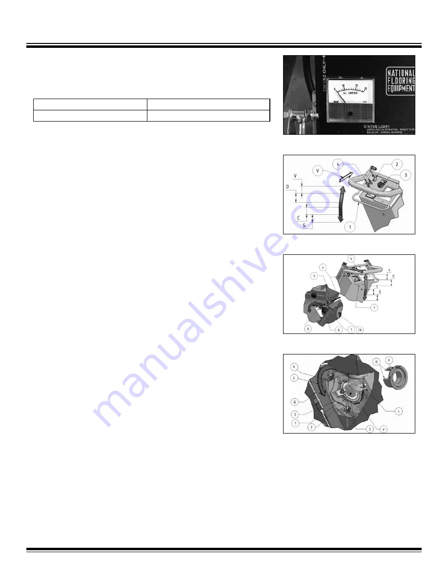
AMP METER
The Amp meter (Figure 1) shows the load consumption of the blast wheel motor. When
turning on the motor, the current is high (starting current peak). For no-load current and
operating current, see the following values:
No Load
Operating
< 10 Amps
23 Amps
PHASE REVERSE
The phase reverse, which is integrated in the main plug, adjusts the direction of rotation
of the wheel motor. Before using machine at each job site, verify the rotation direction of
the blast wheel motor. Reverse rotation will result in premature wear and poor perfor
-
mance. Motor rotation can be observed through openings in the fan cover. Motor must
rotate in the direction indicated by the arrow on the fan cover.
If motor is found to be running backwards:
1.
Turn off control power; wait for motor to stop.
2.
Turn FWD/REV switch to the opposite position.
3.
Turn on control power and blast wheel. Verify motor now rotates correctly.
COMB LEVER - TRACTION DRIVE (FIGURE 2)
This lever (1) is located above the panel and turns on a microswitch (2) that will start or
stop the tracton drive. If this lever is lifted slightly upwards, the traction drive motor will
start up and the machine will move forward, towards direction V. The speed depends
on the setting of the potentiometer (3). Lowering the lever (1) to area S will cause the
traction drive to stop. Lifting the lever further upwards into area O will open the abrasive
control valve (7) via the installed control cable (4).
COMB LEVER - ABRASIVE CONTROL VALVE (FIGURE 3)
To regulate the flow of abrasive to the blast wheel there is a magnetic valve (7) fitted
between the storage hopper (5) and feed spout (6). This valve has a shutter (7A) that
is controlled by the comb lever (1). Changing the shutter position results in a different
amount of abrasive flowing to the blast wheel. Feeding more abrasive causes more work
and a higher load on the blast wheel motor.
The load on the motor is indicated by the Amp meter. The max load is 23-25 Amp. Do not
load more abrasive than recommended. Higher load will cause damage to the motor or
cause it to prematurely fail.
THE WHEEL KIT (FIGURE 4)
The blast wheel (1) throws the abrasive to the surface to profile. It is located in a wheel
housing (G), protected by replaceable wear plates (S). The blast wheel is driven by an
electric motor via a belt drive and is mounted on a bearing unit. The correct rotation of
this machine’s blast wheel is counterclockwise (L).
At the center of the blast wheel is a pre-accelerator called an impeller (2), which feeds
dosed quantities of abrasive onto the blades of the blast wheel. The abrasive has to pass
through the opening (O) of the control cage (3).
This control cage (3) is held by two clamps (4) and needs to be adjusted so the flow of
FIG. 3
FIG. 4
FIG. 1
7


