background image

National Communications

    Page  11

POWER CONTROL UNIT

AS/NZS3260 Approval Number Q00217

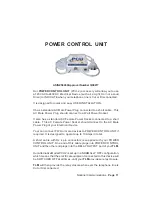
Our 

POWER CONTROL UNIT 

(PCU-2) accessory will allow you to use

a 120VAC to 240VAC Electrical Device ( such as a Light, Horn or a Loud
Siren) to INDICATE when your telephone line is Cut or Disconnected.

It is designed for quick and easy USER INSTALLATION.

It has a standard AC Male Power Plug connected to a short cable.  This
AC Male Power Plug should connect to a Wall Power Socket.

It also has a standard AC Female Power Socket connected to a short
cable.  This AC Female Power Socket should connect to the AC Male
Power Plug of your Electrical Device.

Your can connect TWO or more devices to POWER CONTROL UNIT if
required. It is designed to operate up to 10Amps in total.

A short cable with RJ 4 pin connectors is supplied with your POWER
CONTROL UNIT. One end of this cable plugs into POWER CONTROL
UNIT and the other end plugs into the RELAY OUTPUT port of your 

TLM

.

Our Alternative Model PCU2  is set up in a NORMALLY OFF configuration,
which means that the electrical equipment connected to this device will
be SWITCHED OFF at all times, until your 

TLM

 provides a relay closure.

TLM

 will then provide the relay closure whenever the telephone line is

Cut or Disconnected.

Summary of Contents for Telephone Line Monitor

Page 1: ...Telephone Line Monitor USER GUIDE For Technical Assistance Please Phone 07 5596 5128 ...

Page 2: ...he contacts of an Internal Relay which in turn can be used to trigger other external equipment to advise of the loss of Telephone Line The contact of the Internal Relay will remain closed until the telephone line service has been restored TLM s Internally Relay has Dry Relay Contacts rated at 12V 1A Three Optional low cost Accessories are available from Natcomm for use with TLM to alert the user t...

Page 3: ...onnected to all Telephone sockets on the Telephone Line c This installation procedure MUST be carried out by a suitably qualified telephone technician d This will ensure that there are NO Parallel connected Telephone Devices used on the same line which would cause TLM to respond as if the Telephone Line was Cut or Disconnected POWERCONNECTION A 12VAC Power Adaptor is supplied with TLM It can also ...

Page 4: ...device If you are connecting a NATCOMM Accessory refer to pages 5 11 If you are connecting a THIRD PARTY ELECTRICAL Accessory refer to pages 12 15 An interface box with 2 screw terminals is supplied to provide a convenient means of connecting your 3rd Party Electrical Device to the Relay contacts located within TLM A short connection lead is also supplied to connect the connection box to TLM Impor...

Page 5: ...ult if the polarity of the Red and Red Black wires is not maintained 2 Siren Speaker with Volume Control The Strobe Light accessory connects to the Relay Output port of TLM via the Connection Box and short cable supplied with this accessory A 10 metre cable is supplied with this accessory that can be shortened or lengthened as necessary Please Note Wiring polarity IS VERY important for this Access...

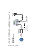
Page 6: ...ions NATCOMM STROBE LIGHT ACCESSORY INSTALLATION RED BLACK Analogue Extension PSTN Line or IP Analogue Adaptor Supplied Strobe Connection Box CONNECTION WITH NATCOMM SUPPLIED STROBE 12V Power Supply Telephone line out to handset ...

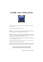
Page 7: ...is supplied connected to the Positive Red and Negative Red Black wires of the Strobe Accessory using a connection block You can lengthen or shorten this cable but it is VERY IMPORTANT that you maintain polarity of the wires The Red wire from the Connection Box must connect to Red wire connected to the Strobe Accessory only The Black Red wire Red wire with Black stripe from the Connection Box must ...

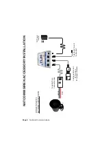
Page 8: ...ications NATCOMM SIREN ACCESSORY INSTALLATION RED BLACK Analogue Extension PSTN Line or IP Analogue Adaptor Supplied Siren Connection Box CONNECTION WITH NATCOMM SUPPLIED SIREN 12V Power Supply Telephone line out to handset ...

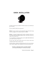
Page 9: ...plied connected to the Positive Red and Negative Black wires of the Siren Accessory using a connection block You can lengthen or shorten this cable but it is VERY IMPORTANT that you maintain polarity of the wires The Red wire from the Connection Box must connect to Red wire connected to the Siren Accessory only The Black Red wire Red wire with Black stripe from the Connection Box must connect to B...

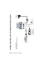
Page 10: ... National Communications Analogue Extension PSTN Line or IP Analogue Adaptor CONNECTION WITH NATCOMM POWER CONTROL UNIT 12V Power Supply Telephone line out to handset POWER CONTROL UNIT ACCESSORY INSTALLATION ...

Page 11: ...short cable This AC Female Power Socket should connect to the AC Male Power Plug of your Electrical Device Your can connect TWO or more devices to POWER CONTROL UNIT if required It is designed to operate up to 10Amps in total A short cable with RJ 4 pin connectors is supplied with your POWER CONTROL UNIT One end of this cable plugs into POWER CONTROL UNIT and the other end plugs into the RELAY OUT...

Page 12: ... two terminals Red Green Telephone line in TLM Relay Output is Dry Contacts rated at 12V 1A maximum Customer device that only requires a Dry Contacts closure Telephone line out to handset 12V Power Supply CONNECTION WITH CUSTOMER SUPPLIED ACCESSORY THAT ONLY REQUIRES A DRY CONTACTS CLOSURE ...

Page 13: ...ired A Connection Box with a short cable to connect it to TLM is provided to allow for quick and easy connection to the external 3rd part device The Connection Box has 2 screw terminals for cable connection to the external 3rd part device The Connection Box screw terminals also connect to the centre 2 pins of the 4P4C RJ socket of TLM See the diagram on page 12 for further detail If your 3rd party...

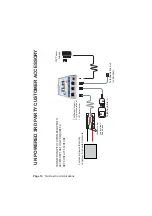
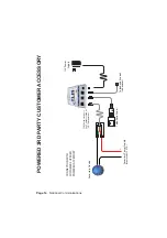
Page 14: ...n Accessory Device TLM Relay Output is Dry Contacts rated at 12V 1A maximum Accessory Power Supply maximum 12V 1A Telephone line out to handset 12V Power Supply CONNECTION WITH CUSTOMER SUPPLIED POWERED ACCESSORY POWERED 3RD PARTY CUSTOMER ACCESSORY ...

Page 15: ...to allow for quick and easy connection of this power source The Connection Box screw terminals will then connect the power source to one of the centre 2 pins of the 4P4C RJ socket of TLM When the TLM relay closes power will then output through the other centre pin of the 4P4C RJ socket of TLM to the remote electrical device When the relay opens this power flow will be removed See the diagram on pa...

Page 16: ...nd a written statement about the nature of the problem This Warranty shall not apply to any unit which has been subject to alteration modification abuse negligence accident external voltage lightning surge or used in any manner contrary to these instructions The obligation is solely to repair or replace the product The warrantor is not liable for any incidental or consequential damages due to such...

Reviews: