background image


5

www.napoleongrills.com

Leak Testing Instructions

WARNING!

  A leak test must be performed annually and each time a cylinder is hooked up or if a part 

of the gas system is replaced.  

WARNING!

 Never use an open flame to check for gas leaks. Be certain no sparks or open flames are 

in the area while you check for leaks.  Sparks or open flames will result in a fire or explosion, damage to 

property, serious bodily injury, or death.

Leak testing

:  This must be done before initial use, annually, and whenever any gas components are replaced 

or serviced. Do not smoke while performing this test, and remove all sources of ignition. See Leak Testing Diagram 

for areas to check. Turn all burner controls to the off position. Turn gas supply valve on.  

Brush a half-and-half solution of liquid soap and water onto all joints and connections of the regulator, 

hose, manifolds and valves.
Bubbles will indicate a gas leak. Either tighten the loose joint or have the part replaced with one recommended 

by the Napoleon Customer Care department and have the grill inspected by a certified gas installer.
If the leak cannot be stopped, immediately shut off the gas supply, disconnect it, and have the grill inspected 

by a certified gas installer or dealer. Do not use the grill until the leak has been corrected. 

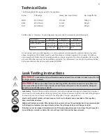
Technical Data

The following table lists input values for the appliance.
Burner   

Orifice Size 


(Gross) Heat Input (Total)   

Gas Usage (Total)  


MAIN   

58 (1.07mm) 


19.2 kW   


1396 g/h

BACK    

58 (1.07mm) 


5.3 kW    


385 g/h

SIDE 


66 (0.84mm) 


2.8 kW   


204 g/h

Certified Gases / Pressures - Check rating plate to ensure that it corresponds with following list.

Do not tamper with or modify regulator. Use only regulators, which supply the pressure, listed in the table 

above. A regulator of 28-30mbar must be used for butane or a 37mbar regulator for propane. For grills set 

up to operate at 50mbar, the grill is equipped with an internal regulator. This internal regulator has an outlet 

pressure of 30mbar and must not be modified or adjusted. For replacement, use only the regulator specified 

by the manufacturer: Maxitrol model number RV47LSMF.

Gas Category

I

3B/P(30)

I

3+(28-30/37)

I

3B/P(50)

Orifice Sizes (see above)

I

I

I

Gases / Pressures

Butane 30mbar 

Propane 30mbar

Butane 28-30mbar 

Propane 37mbar

Butane 50mbar 

Propane 50mbar

Countries

DK, FI, NL, NO, 

SE

BE, ES, FR, GB, IE, 

IT, PT

DE, AT

Summary of Contents for MIRAGE 605

Page 1: ...ff gas to the appliance Extinguish any open flame Open lid If odor continues keep away from the appliance and immediately call your gas supplier or fire department APPLY SERIAL NUMBER LABEL FROM CARTO...

Page 2: ...this President s Limited Lifetime Warranty NAPOLEON may at its discretion fully discharge all obligations with respect to this warranty by refunding to the original warranted purchaser the wholesale...

Page 3: ...eing stored indoors Inspect the gas line hose before each use If there is evidence of excessive abrasion or wear it must be replaced before using the gas grill with a replacement hose assembly specifi...

Page 4: ...s kink free Remove the cap or plug from the cylinder fuel valve Tighten regulator to cylinder valve Leak test all joints prior to using the barbecue A leak test must be performed annually and each tim...

Page 5: ...d gas installer If the leak cannot be stopped immediately shut off the gas supply disconnect it and have the grill inspected by a certified gas installer or dealer Do not use the grill until the leak...

Page 6: ...n turn light the burner If the pilot lights continue to push down on the burner control knob until the burner lights then release 3 If the burner does not ignite then immediately turn the control knob...

Page 7: ...om the wind The recommended pan diameter is 200 to 250 mm WARNING Never grill food directly on the side burner grate It is designed for use with pots and pans only Infrared Main Burner Use If Equipped...

Page 8: ...al gas burners heat the food in a different way The air surrounding the burner is heated by the combustion process and then rises to the food being cooked This generates lower grill temperatures that...

Page 9: ...trol Panel The control panel text is printed directly on the stainless steel and with proper maintenance will remain dark and legible To clean the panel use only warm soapy water or stainless steel cl...

Page 10: ...re must taken to prevent cracking of their ceramic surfaces Fractures will cause the burners to malfunction The following provides a few of the causes of cracks and the steps you can take to avoid the...

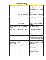
Page 11: ...erformance or safety of the gas grill Humming regulators will not be replaced Burners will not cross light each other Plugged ports at back of burner Clean burner ports See burner maintenance instruct...

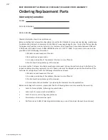
Page 12: ...ion of the problem broken is not sufficient 4 Proof of purchase photocopy of the invoice In some cases the Customer Care Representative could request to have the parts returned to the factory for insp...

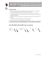
Page 13: ...rill has been fully assembled and operates to your satisfaction 3 Assemble the grill where it is to be used lay down cardboard or a towel to protect parts from being lost or damaged while assembling 4...

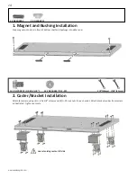
Page 14: ...each caster Attach brackets under front casters as illustrated Tighten securely 1 Magnet and Bushing Installation Snap magnets into slots in front of bottom shelf and bushings into either end 2 X N430...

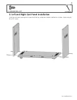
Page 15: ...ls com 4 x N570 0080 14 x 1 2 3 8 10mm 3 Left and Right Cart Panel Installation Install end cart panels ensuring slots in panel are to the top rest panel on bottom shelf and line up holes Fasten using...

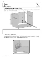
Page 16: ...re large hole in panel is to the bottom right corner as illustrated Fasten using 6 14 x 1 2 screws three on each side 5 Condiment Basket Rotate basket slightly to allow wire to enter the holes in the...

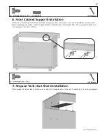
Page 17: ...using 4 14 x 1 2 screws For ease of installation start all screws before tightening completely Attach magnet brackets to bottom of top rail using 2 14 x 1 2 screws per bracket and snap magnets into pl...

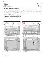
Page 18: ...gulator hose during shipping and is no longer required Take care when removing the tie not to damage the hose Ensure the regulator drops into the small opening between the tank heat shield and the rig...

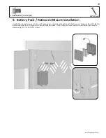
Page 19: ...Installation Install battery pack below vent slots on left hand panel using magnet supplied with battery pack Plug wire from LED lights located underneath control panel into wire from battery pack In...

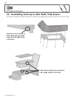
Page 20: ...t head screw driver insert screw through tab and into end cap Tabs located on either side of ice bucket must engage notches in side shelf 10 Assembling End Caps to Side Shelf Side Burner Peel protecti...

Page 21: ...e Burner Installation Insert 4 20 x 5 8 screws through the washers into the threaded holes in the side of the base do not tighten all the way Slide the assembled side burner over the screw heads and f...

Page 22: ...ascia to center of support beam Slide top of fascia up under support beam as shown resting bottom on bottom shelf Fasten with 4 14 x 1 2 screws 14 Tank Inhibitor Rod Installation Insert one end of tan...

Page 23: ...onto front of door using 2 1 4 20 x 3 8 screws per door and 2 1 4 lock washers per door Insert pivot rod through hole on inside top of door Holding door in one hand direct pivot rod into hole in under...

Page 24: ...be burner with slots down to allow drippings to travel through 3 x N305 0057 17 Grids and Warming Rack Installation Position grids and warming rack into base as shown Rest warming rack on brackets ins...

Page 25: ...grease tray holder into the two holes located in the center of the back panel Place the aluminum grease tray into the grease tray holder 19 Drip Pan Installation Slide drip pan into rear of base as s...

Page 26: ...26 www napoleongrills com Rotisserie Kit Assembly Instruction optional Assemble rotisserie kit components as shown Ensure stop bushing is tightened on the inside of hood casting...

Page 27: ...tank heat shield and the right side of the cabinet Clip hose to side panel using hose retainer clip supplied Propane Only Improper Hose Connection WARNING FIRE HAZARD The regulator must be attached so...

Page 28: ...d Do not smoke while performing this test and remove all sources of ignition See Leak Testing Diagram for areas to check Turn all burner controls to the off position Turn gas supply valve on Brush a h...

Page 29: ...eel side shelf right x 20 N120 0009 LUXIDIO side shelf end cap right x 21 N570 0080 14 x 1 2 screw x 22 N010 0616 stainless steel side shelf left x 23 N120 0008 LUXIDIO side shelf end cap left x 24 N5...

Page 30: ...002 switch light x 62 N190 0001 battery pack x W043 0002 battery AA x 64 N735 0001 insulated washer x N105 0001 bushing 7 8 x 66 N640 0001 hose retainer clip x 68 N130 0012 revolving caster x 69 N450...

Page 31: ...13 14 15 16 17 18 20 19 14 22 23 24 25 26 27 28 29 30 31 32 33 34 35 36 37 38 39 40 41 42 43 44 45 46 47 47 48 48 49 49 50 50 52 53 54 55 56 57 59 59 59 59 61 62 64 66 68 69 72 76 77 57 64 3 21 21 21...

Page 32: ..._________________________________________________________________________________________ TEL _________________________________ FAX ______________________________ EMAIL _______________________________...

Page 33: ...EFAHR WENN ES NACH GAS RIECHT Gaszufuhr zum Ger t absperren Flammen l schen Haube ffnen Wenn es weiterhin nach Gas riechen sollte dem Ger t fernbleiben und unverz glich den Gaslieferanten oder die Feu...

Page 34: ...LEON dass ihre Produkte frei von Verarbeitungsfehlern sind Dabei gelten folgende Bedingungen und Beschr nkungen Die Herstellergarantie ist nicht bertragbar und kann auf keinen Fall von einem unserer V...

Page 35: ...er N he des Grills aufbewahren Die Gasflasche niemals mehr bis als 80 f llen Versuchen Sie nicht eine Gasflasche zu verwenden die nicht mit einer Verbindung vom Typ QCC1 ausgestattet ist Vor der erste...

Page 36: ...h nach jedem Anschlie en einer Flasche und nach Auswechseln eines Gasbauteils durchgef hrt werden ACHTUNG Schlauch nicht unterhalb der Auffangschale verlegen Schlauch nicht im Zwischenraum zwischen de...

Page 37: ...opane 30mbar Butane 28 30mbar Propane 37mbar Butane 50mbar Propane 50mbar L nder DK FI NL NO SE BE ES FR GB IE IT PT DE AT Anleitung F r Die Leckagepr fung ACHTUNG Ein Leckagetest muss vor der ersten...

Page 38: ...nnt 3 Wenn der Brenner nicht z ndet das Bedienelement SOFORT wieder auf OFF Aus stellen und Schritt 2 mehrmals wiederholen 4 Falls Pilot und Brenner nicht innerhalb von 5 SEKUNDEN z nden das Bedienele...

Page 39: ...eisch von der Flamme weg zur Seite und stellen die Temperatur herunter Lassen Sie die Haube offen Eine detaillierte Anleitung finden Sie in Napoleons Grill Kochbuch Direktes Garen Grillgut direkt ber...

Page 40: ...verleiht Die Infrarotbrenner der Napoleon Grills funktionieren genauso Jeder der Brenner hat 10 000 L cher Aus jedem Loch tritt eine Flamme aus die die Keramikoberfl che zur Rotglut bringen Die gl hen...

Page 41: ...ite auf h chster Stufe dann mittlere bis unterste Stufe 20 25 Min Gelenk zwischen Ober und Unterschenkel auf der hautlosen Seite durchschneiden damit das Fleisch flach auf dem Grill liegt So wird es s...

Page 42: ...die Edelstahloberfl che gedruckt und bei sachgerechter Pflege bleibt der Aufdruck dunkel und lesbar Zur Reinigung der Bedienleiste warme Seifenlauge oder Edelstahlreiniger verwenden Edelstahlreiniger...

Page 43: ...istet ist muss verhindert werden dass die Keramikbeschichtung rei t Im Folgenden wird beschrieben wie Rissbildung zu verhindern ist Sch den die wegen Nichtbeachtung dieser Hinweise auftreten sind nich...

Page 44: ...Siehe Zusammenbauanleitung Grill mit beiden Hauptbrennern auf h chster Stufe 10 15 Minuten lang vorw rmen Anbratplatten und Tropfpfanne regelm ig reinigen Tropfpfanne nicht mit Alufolie auslegen Siehe...

Page 45: ...Keramikfliese undicht oder Schwei ung im Brennergeh use defekt Brenner abstellen und mindestens zwei Minuten lang abk hlen lassen Brenner erneut z nden und so lange auf h chster Stufe brennen lassen e...

Page 46: ...des Ger ts 2 Teilenummer und beschreibung 3 Vollst ndige Beschreibung des Problems kaputt ist nicht ausreichend 4 Kaufnachweis Fotokopie der Rechnung In manchen F llen kann der Kundendienstbeauftragt...

Page 47: ...st ren Sie die Verpackung nicht bevor der Grill vollst ndig montiert ist und zu Ihrer Zufriedenheit funktioniert 3 Den Grill an der Stelle montieren wo er verwendet werden soll Legen Sie Pappe oder ei...

Page 48: ...en Anschlagwinkel unter halb der vorderen Lenkrollen anbringen wie unten abgebildet Festziehen 1 Installation der T rscharnier Buchse und Magneten Snap Magneten in die Schlitze vor der unteren Regal u...

Page 49: ...n der linken und rechten Seitenpaneele des Wagens Die Seitenpaneele des Wagens mit den Schlitzen nach oben installieren Hierzu das Seitenpaneel auf den unteren Regalboden aufsetzen und ausrichten bis...

Page 50: ...o e Loch rechts unten befindet wie abgebildet Mit sechs Nr 14 x 1 2 Schrauben befestigen drei auf jeder Seite 5 Gew rzhalter Den Gew rzhalter leicht drehen um die Enden der Haltedr hte in die vorgeseh...

Page 51: ...hen und erst festdrehen wenn der Schrank richtig montiert und ausgerichtet ist Magnethalter mit zwei Nr 14 x 1 2 Schrauben an der Unterseite der Leiste montieren und Magnete wie gezeigt einschnappen l...

Page 52: ...erung ab Werk angebracht um den Schlauch des Druckreglers vor Besch digung zu sch tzen und ist nicht weiter erforderlich Den Kabelbinder vorsichtig durchschneiden um den Schlauch nicht zu besch digen...

Page 53: ...fach mit dem beiliegenden Magnet am linken Seitenpaneel unterhalb der L ftungsschlitze anbringen Das LED Kabel Beleuchtung unterhalb der Bedienleiste mit dem Kabel des Batteriefachs verbinden Die Halt...

Page 54: ...die Lasche und in die Abschlusskappe f hren Die gestanzten Streifen an beiden Seiten des Eisbeh lters werden schl ssig in die Aussparungen der Seitenablage eingesetzt 10 Montieren der Abschlusskappen...

Page 55: ...Seitenbrenners Vier 1 4 20 x 5 8 Schrauben mit Belegscheiben in die L cher mit Gewinde an der Seite des Grillaufsatzes einschrauben Nicht ganz festdrehen Komplett montierten Seitenbrenner ber die Sch...

Page 56: ...en Das obere Ende der Verkleidung wie gezeigt unter die Leiste schiedben wobei das untere Ende auf dem unteren Regalboden aufliegt Mit vier Nr 14 x Schrauben befestigen 14 Installation der Tankarretie...

Page 57: ...und zwei 1 4 Federringen pro T r installieren Drehstange durch das Loch an der inneren T roberseite f hren T r mit einer Hand halten und Drehstange in das das Loch an der Unterseite des Vordertr gers...

Page 58: ...tzen nach unten damit tropfendes Fett ablaufen kann 3 x N305 0057 17 Installation Grill und Warmhalterost Grillroste und Warmhalterost wie gezeigt in den Aufsatz einsetzen Warmhalterost auf den Winkel...

Page 59: ...in der Mitte des r ckseitigen Panels einstecken Den Aluminium Fett Auffangbeh lter in den Halter einsetzen 19 Installation der Auffangschale Auffangschale in die R ckseite des Grillaufsatzes einschieb...

Page 60: ...ngrills com Anweisungen f r die Montage des Drehspie Sets optionale Komponenten des Drehspie Sets wie gezeigt montieren Sicherstellen dass die Anschlagbuchse an der Innenseite des Haubengussteils fest...

Page 61: ...chten Schrankseite befindet Schlauch Mit Dem Mitgelieferten Schlauchhalterclip Am Seitenpanel Befestigen Nur F r Propangas Inkorrekter Schlauchanschluss ACHTUNG FEUERGEFAHR Der Schlauch des Druckregle...

Page 62: ...e Z ndquellen sind zu entfernen Die zu pr fenden Stellen sind auf der Leckagepr fzeichnung aufgef hrt Alle Brenner abstellen Flaschenventil aufdrehen Seifenwasser halb Wasser halb Fl ssigseife auf all...

Page 63: ...8 N305 0057 M03 Gl hplatte x 19 N010 0586 Edelstahl Seitenablage rechts x 20 N120 0009 LUXIDIO Abschlusskappe f r Seitenablage rechts x 21 N570 0080 Nr 14 x 1 2 Schraube x 22 N010 0616 Edelstahl Seite...

Page 64: ...N430 0002 Magnetschnapper x N370 0549 Montagematerial Beutel x 60 N080 0210 Stabilisierungsleiste x 61 N750 0021 Kabelf hrung LED x N660 0002 Schalter Beleuchtung x 62 N190 0001 Batteriefach x W043 00...

Page 65: ...65 www napoleongrills com x Standard ac Zubeh r St ckliste Position Teilenr Beschreibung 605 56018 Edelstahlgrillplatte ac 67730 Holzkohlenwanne ac 62007 Ersatz Fett Auffangbeh lter 5 St ck ac...

Page 66: ...13 14 15 16 17 18 20 19 14 22 23 24 25 26 27 28 29 30 31 32 33 34 35 36 37 38 39 40 41 42 43 44 45 46 47 47 48 48 49 49 50 50 52 53 54 55 56 57 59 59 59 59 61 62 64 66 68 69 72 76 77 57 64 3 21 21 21...

Page 67: ..._________________________________________________ TELEFON _________________________________ FAX ______________________________ EMAIL __________________________________________________________________...

Page 68: ...N415 0197CE GB DE...
Reviews: