


EN
11
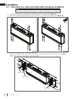
installation
W415-4188 / B-0 / 11.13.23
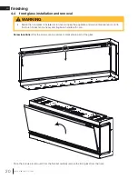
2.1 minimum mantel clearances
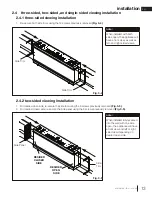
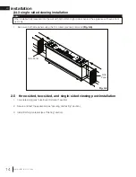
2.2 rough framing
• When using paint or lacquer to finish the mantel, the paint or lacquer must be heat resistant to
prevent discolouration.
WARNING
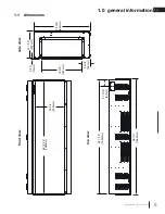
Measurements are taken from
the top of the appliance:
Bottom, Sides,
and Back
0”
Top
0” recessed into wall and
3 9/16” (90mm) to mantel
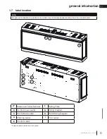
• Non-load bearing wall framing
• Hard wire location
Appliance is NOT load-bearing. Carefully
consider the weight of finishing materials
when constructing rough framing.
note:
Ensure the installation complies with all
local building codes and requirements.
Profile View
25 7/8”
(657mm)
12 1/2”
(318mm)
A
Insulation
Image is for illustrative
purposes only.
Drywall
MANTEL
TOP OF
APPLIANCE
FINISHING
MATERIAL
APPLIANCE
FINISHING
EDGE TRIM
WALL
3 9/16”
90mm
Dimensions
Installation Type
A (Framing Opening Width)
Single Sided Viewing
65 9/16” (1665mm)
Two and Three Sided
Viewing
65 1/16” (1653mm)


