W415-1066 / A / 03.06.12
19
• using the self drilling screws, mount switch and bracket as per diagram.
• connect harness wiring to switches as per picture:
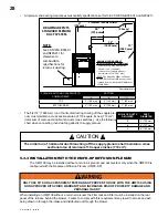
7/8” diAmeTer hole
SuPPly Plenum
8
7
9
high limiT 250°f
(121°c)
fAn on 165°f
(74°c)
fAn off 110°f
(43°c)
10"
10"
(51 mm)
(51 mm)
(254 mm)
(254 mm)
2"
2"
SuPPly Plenum
hole locATion
When Air filTer
brAckeT iS
inSTAlled on
lefT Side PAnel
hole locATion
When Air filTer
brAckeT iS
inSTAlled on
righT Side PAnel
righT Side PAnel
lefT Side PAnel
NOTE
if rear installation is chosen for the fan/limit switch, 24” (610 mm) service clearance is required at the side of
the unit the fan/limit switch is located on.


