background image

8

WS-415-63 / 11.24.98

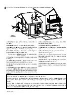
(A) 

Flush ( 0 inches) 

with outside non-combustible cor-

ner walls.

Two inches 

from outside combustible corner walls.

(B) 

Flush ( 0 inches) 

with inside corner walls or protrud-

ing non-combustible obstructions (chimney, etc)

Two inches 

from inside corner walls or protruding com-

bustible obstructions (vent chase, etc)

The periscope requires a minimum 18" clearance from

an inside corner.

(C) 

Two feet 

from adjacent walls, including neighbouring

buildings.

(D) 

One foot 

from the sides, top and bottom of a non-

mechanical combustion or ventilation air supply.

(E) 

Six feet

 from mechanical combustion or ventilation

air supplies.

(F) 

One foot 

to an unventilated soffit located above the

terminal or 

eighteen inches

 to a ventilated soffit located

above the terminal, provided the soffit is sealed for a dis-
tance of 24 inches either side of the centre line of the
terminal.

The air terminal must be located with the minimum clearances as illustrated in 

FIGURE 9:

FIGURE 9

(G) 

Seven feet 

above public walkways unless fitted

with heat shield kit GD301.

(H) 

One foot 

below windows that open.

(I) 

One foot 

from the side of doors and windows that

open.

(J) 

One foot 

from permanently closed windows.

(K) 

One foot

 above grade.

(L)


NOT above a regulator/meter assembly or within

three feet 

horizontally


from the vertical centre-line

of the assembly.

(M) 

Six feet 

from a gas service regulator vent outlet.

(N) 

Sixteen inches 

above the roof.

(O) 

One foot 

to the underside of a veranda, porch,

deck or balcony that has a minimum of two open
sides.

*

All horizontal runs, runs must have a minimum 1 inch rise per foot.
A terminal shall not terminate directly above a sidewalk or paved driveway which is located betweeen two

single family dwellings and serves both dwellings. Local codes or regulations may require different clear-

ances.
Do not allow the inside liner to bunch up on horizontal or vertical runs and elbows. Keep it pulled tight.

A 1¼" air gap all around between the inner liner and outer liner is required for safe operation. Use a

firestop when penetrating interior walls, floor or ceiling.

Summary of Contents for GDS 3700-P

Page 1: ...722 6031 Email ask napoleon on ca Web www napoleon on ca Wolf Steel Ltd RR 1 9 Napoleon Rd Barrie ON Canada L4M 4Y8 705 721 1212 R 2000 Immediately call your gas supplier from a neighbour s phone Follow the gas supplier s instructions If you cannot reach your gas supplier call the fire department W W W W WARNING ARNING ARNING ARNING ARNING If the information in these instructions is not followed e...

Page 2: ...rtical Venting Installation Stove Vent Connection 10 10 10 10 10 GAS INST GAS INST GAS INST GAS INST GAS INSTALLA ALLA ALLA ALLA ALLATION TION TION TION TION 11 11 11 11 11 FINISHING FINISHING FINISHING FINISHING FINISHING Log Placement Charcoal Embers PG PG PG PG PG 12 12 12 12 12 OPERA OPERA OPERA OPERA OPERATION MAINTENANCE TION MAINTENANCE TION MAINTENANCE TION MAINTENANCE TION MAINTENANCE Ope...

Page 3: ...pproval of an authorized company official Labour costs work however requires the prior approval of an authorized company official Labour costs to the account of to the account of to the account of to the account of to the account of NAPOLEON NAPOLEON NAPOLEON NAPOLEON NAPOLEON are based on a predetermined rate schedule and any repair are based on a predetermined rate schedule and any repair are ba...

Page 4: ... or the ANSI NFPA 70 1990 NATIONAL ELECTRICAL CODE in the United States The blower power cord must be connected into a properly grounded receptacle The grounding prong must not be removed from the cord plug Provide adequate ventilation and combustion air Provide adequate accessibility clearance for servicing and operating the stove Never obstruct the front opening of the stove GENERAL INFORMA GENE...

Page 5: ...nts burners and circulating blower and its passageway in the stove and venting system are kept clean The stove and its venting system should be inspected before use and at least annually by a qualified service person More frequent cleaning may be required due to exces sive lint from carpeting bedding material etc The stove area must be kept clear and free from combustible materials gasoline and ot...

Page 6: ...SE IMMEDI AL RUN WITH A 57 INCH VERTICAL RISE IMMEDI AL RUN WITH A 57 INCH VERTICAL RISE IMMEDI AL RUN WITH A 57 INCH VERTICAL RISE IMMEDI AL RUN WITH A 57 INCH VERTICAL RISE IMMEDI A A A A ATEL TEL TEL TEL TELY ABOVE THE STOVE IS 20 FEET Y ABOVE THE STOVE IS 20 FEET Y ABOVE THE STOVE IS 20 FEET Y ABOVE THE STOVE IS 20 FEET Y ABOVE THE STOVE IS 20 FEET IF VERTICAL RISES GREA IF VERTICAL RISES GREA...

Page 7: ...LA ALLA ALLA ALLATION EXAMPLE TION EXAMPLE TION EXAMPLE TION EXAMPLE TION EXAMPLE If a first run of 48 inches is required using the First Vent Run chart shows that a 51 inch vertical rise is necessary and a maximum second run of 32 inches is allowable IF NECESSAR IF NECESSAR IF NECESSAR IF NECESSAR IF NECESSARY Y Y Y Y THE FIRST RUN AND THE SECOND RUN MA THE FIRST RUN AND THE SECOND RUN MA THE FIR...

Page 8: ... as illustrated in FIGURE 9 FIGURE9 G Seven feet above public walkways unless fitted with heat shield kit GD301 H One foot below windows that open I One foot from the side of doors and windows that open J One foot from permanently closed windows K One foot above grade L NOT above a regulator meter assembly or within three feet horizontally from the vertical centre line of the assembly M Six feet f...

Page 9: ... 12 3 Slip the first section of 7 diameter stove pipe a minimum of 2 over the outer sleeve of the air terminal Secure to the sleeve using 3 screws Seal the joint and screw heads using high temperature sealant 4 Install the firestop wall plate to the finished interior wall maintain ing a 1 clearance to combustibles Insert the liners through the firestop Holding the air terminal lettering in an upri...

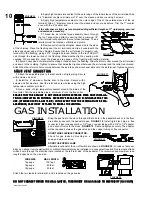
Page 10: ...E INSTALLA ALLA ALLA ALLA ALLA TION IS COMPLETED AN OPTIONAL DECORA TION IS COMPLETED AN OPTIONAL DECORA TION IS COMPLETED AN OPTIONAL DECORA TION IS COMPLETED AN OPTIONAL DECORA TION IS COMPLETED AN OPTIONAL DECORATIVE BRASS BAND IS A TIVE BRASS BAND IS A TIVE BRASS BAND IS A TIVE BRASS BAND IS A TIVE BRASS BAND IS AV V V V VAILABLE FOR THIS AILABLE FOR THIS AILABLE FOR THIS AILABLE FOR THIS AILA...

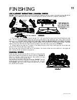
Page 11: ...cated on the rear wall of the combustion chamber The notch situated at the lower left of the back log should be centered evenly above the pilot assembly FIGURE 21 3 While supporting the back log to prevent it from falling forward set the three smaller logs into the pockets and grooves of the front and back logs respectively Log colours may vary During the initial use of the fireplace the colours w...

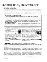
Page 12: ...s supplier from a neighbour s phone Follow the gas supplier s instructions If you cannot reach your gas supplier call the fire department FOR YOUR SAFETY READ BEFORE OPERATING A This fireplace is equipped with a pilot which must be lit by hand while following these instructions exactly B Before operating smell all around the fireplace area for gas and next to the floor because some gas is heavier ...

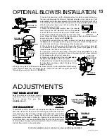
Page 13: ...d will run for approximately 30 minutes after the stove has been turned off Use of the fan in creases the output of heat 1 Mount the variable speed switch insert the rheostat stem through the 3 8 diameter hole in the pedestal and from the front secure with the pal nut Add the knob 2 Remove the blower housing located at the rear of the stove Attach the bracket holding the heat sensor as shown to th...

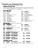
Page 14: ...ISCOPE TERMINAL KIT GD180 PERISCOPE TERMINAL KIT GD180 PERISCOPE TERMINAL KIT PART PART PART PART PART DESCRIPTION DESCRIPTION DESCRIPTION DESCRIPTION DESCRIPTION PART PART PART PART PART DESCRIPTION DESCRIPTION DESCRIPTION DESCRIPTION DESCRIPTION BM6790 90 ELBOW 7 DIAMETER GD201 PERISCOPE BM67ADJ 30 TO 53 ADJUSTABLE PIPE 7 DIAMETER GDS 500 77 FIRESTOP WALL PLATE GDS 020 32 HARDWARE BRTC7 BRASS TR...

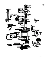
Page 15: ...15 WS 415 63 11 24 98 included with GD180 included with GD175 I H L O L F F N T I O O P O ...

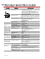
Page 16: ...cooled Allow approximately 60 seconds for the thermocouple to cool Pilot flame is not large enough turn up the pilot flame Pilot flame is not engulfing the thermocouple turn up pilot flame replace pilot assembly Thermocouple shorting loosen and tighten thermocouple clean thermocouple and valve connection replace thermocouple replace valve Faultly thermocouple replace Faulty valve replace System is...

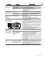
Page 17: ...emoved as required refer to Figure 16 to ensure correct location of storm collars Incorrect installation Main burner goes out pilot goes out REFER TO MAIN BURNER GOES OUT PILOT STAYS ON Thermocouple shorting or faulty check joint seals and installation Vent re circulating loosen and tighten thermocouple clean thermocouple and valve connection replace thermocouple replace valve PROBLEM PROBLEM PROB...

Page 18: ...18 WS 415 63 11 24 98 NOTES ...

Reviews: