background image

EN

W415-3006 / A / 05.27.21

41


troubleshooting

!

WARNING

•  Always light the pilot whether for the fi rst time or if the gas supply has run out, with the glass door (where 

applicable) open or removed.

•  Turn off gas and electrical power before servicing the appliance.

•  Appliance may be hot. Do not service until appliance has cooled.

•  Do not use abrasive cleaners

27.9

symptom

problem

test solution

Flames are consistently 

too large or too small. 

Carboning occurs.

Appliance is over-fi red or under-

fi red.


-

Check pressure readings: 

Inlet pressure can be checked by turning screw (A) counter-clock-

wise 2 or 3 turns and then placing pressure gauge tubing over the 

test point. Gauge should read as described on the chart below. 

Check that main burner is operating on ‘HI’. Outlet pressure can be 

checked the same as above using screw (B). Gauge should read as 

described on the chart below. Check that main burner is operating 

on ‘HI’. 

After taking pressure readings, be sure to turn screws 

clockwise fi rmly to reseal. DO NOT OVER TORQUE.

Leak test with a soap and water solution.

Air shutter improperly adjusted.

 -

Return air shutter to factory-set opening.

For propane - improper lighting 

procedure.

For natural gas - undersized 

supply line.

 -

Ensure lighting procedure is followed carefully. The valve must be in 

the off position when the tank valve is turned on. Turn tank on slowly 

to allow pressure to equalize. See lighting instructions.

 -

Pipe must be sized according to installation code.

Burners burn with 

yellow fl ame, accom-

panied by the smell of 

gas.

Possible spider web or other 

debris.

 -

Thoroughly clean burner venturi. See “cleaning / maintenance 

instruction” section.

Carbon is being 

deposited on glass, 

logs, rocks, media, or 

combustion chamber 

surfaces.

Air shutter is blocked.

 -

Ensure air shutter opening is free of lint or other obstructions.

Flame is impinging on the glass, 

logs, rocks, media or combus-

tion chamber.

 -

Ensure the media is positioned correctly in the appliance.

 -

Open air shutter to increase the primary air.

 -

Check the input rate: check the manifold pressure and orifi ce size as 

specifi ed by the rating plate.

White / grey fi lm forms.

Sulphur from fuel is being depos-

ited on glass, logs, or combus-

tion chamber surfaces.

 -

Clean the glass with a recommended gas fi replace glass cleaner. 

DO


NOT CLEAN GLASS WHEN HOT.

 -

If deposits are not cleaned off regularly, the glass may become 

permanently marked.

Pilot will not light. Makes 

noise with no spark at 

pilot burner.

Wiring: short, loose, or damaged 

connections

(poor fl ame rectifi cation).

 -

Verify the thermocouple/sensor is clean and the wiring is undamaged.

 -

Verify the interrupter block is not damaged or too tight. Verify 

connections from pilot assembly are tight; also verify the connections 

are not grounding out to any metal. (Remember, the fl ame carries the 

rectifi cation current, not the gas. If fl ame lifts from pilot hood, the circuit 

is broken. A wrong orifi ce or too high of an inlet pressure can cause the 

pilot fl ame to lift)*. The sensor rod may need cleaning.

No signal from remote with no 

pilot ignition.

 -

Reprogram receiver code.

 -

Replace receiver.

Poor grounding.

 -

Verify the valve and pilot assembly is properly grounded

Improper switch wiring.

 -

Troubleshoot the system with the simplest on/off switch.

Dirty, painted, or damaged pilot 

and/or dirty sensor rod.

 -

Clean sensor rod with a green Scotch-Brite™ pad to remove any 

contamination that may have accumulated. Verify continuity with 

multimeter with ohms set at the lowest range.

INSERT 

PHOTO 

OF VALVE 

HERE

*Maximum inlet pressure not to exceed 13” w.c.

Pressure

Natural Gas

(inches)

Natural Gas

(millibars)

Propane

(inches)

Propane

(millibars)

Inlet 

*7”

(minimum 4.5”)

17.4mb

(minimum 11.2mb)

13”

(minimum 11”)

32.4mb

(minimum 27.4mb)

Outlet 

3.5”

8.7mb

10”

24.9mb

symptom

problem

test solution

Pilot sparks but will not 

light.

Gas supply.

 -

Verify that the incoming gas line ball valve is “open”.

 -

Verify that the inlet pressure reading is within acceptable limits, inlet 

pressures must not exceed 13” W.C.

Out of propane gas.

 -

Fill the tank.

Pilot supply line may contain air.

 -

Repeat ignition process several times or purge the pilot supply line.

Incorrect wiring / grounding.

 -

Ensure correct polarity of wiring of thermocouple (if equipped).

 -

Verify pilot assembly/valve are properly grounded.

Receiver (if equipped).

 -

Reset program: hold reset button on receiver and wait for 2 beeps. 

Release after second beep. Press small fl ame button on remote 

within 20 seconds, you will hear an additional beep (this signals a 

successful reset).

 -

Replace receiver.

Valve.

 -

Check valve and replace if necessary (Do not to overtighten 

thermocouple).

Burner continues to 

spark and pilot lights 

but main burner does 

not light.

Short or loose connection in 

sensor rod.

 -

Verify all connections. Verify the connections from the pilot assembly 

are tight. Also, verify these connections are not grounding out to any 

metal.

Dirty, painted, or damaged pilot 

assembly components.

 -

Clean using a green Scotch-Brite™ pad to remove any 

contamination that may have accumulated on the sensor rod, pilot 

hood, ignitor, or fl ame sensor. Verify continuity with multimeter with 

ohms set at the lowest range.

Remote and / or 

receiver is not 

functioning properly (if 

applicable).

Receiver or remote has low 

battery.

 -

Replace batteries.

Appliance functions but does not 

respond to receiver / remote.

 -

Ensure appliance is being operated by the same device that turned 

it on. Remote controls function if appliance has turned on by remote. 

Receiver controls function if appliance was burned on by receiver.

Error with synchronizing.

 -

Reset receiver and remote.

Remote too far away from receiver.

 -

Refer to “wiring diagram” section.

Wire connector pins are bent.

 -

Straighten pins.

Valve wiring is damaged.

 -

Replace valve harness.

Appliance won't 

perform any 

functions

No power to the system.

 - Check breaker to verify it is in the "on" position.

 - Ensure module is wired to power correctly.

Receiver switch in wrong 

position (if equipped).

 - Verify that the 3-position switch on the receiver is in the 

remote position (middle).

On/off switch in wrong posi-

tion.

 - Verify that the switch is in the "on" position.

Transmitter isn't operational 

(if required).

 - Check battery power and battery orientation.

Light won't function 

(if applicable).

Light bulb burnt out.

 - Change the bulb.

Light harness damaged.

 - Replace the harness.

Switch in wrong position.

 - Ensure switch is in "on" position.

No power to lights.

 - Ensure power transformer is plugged into junction box and 

lights are wired correctly.

If back up batteries are installed, they must also be removed to 

re-program

note:

12.0   troubleshooting

La flamme doit envelopper 

la sonde de flamme de 

3/8" à 1/2" 

(9.5mm - 12.7mm)

Flame must envelop 

upper

3/8" to 1/2" 

(12.7mm - 9.5mm) of

Flame sensor

DEXEN EI   2-WAY PILOT

DEXEN EI

ODS - MILLIVOLT

3/8” - 1/2”

(9.5mm - 12.7mm)

Flame must envelop 

upper

3/8" to 1/2" 

(12.7mm - 9.5mm) of

thermocouple

3/8” - 1/2”

(9.5mm - 12.7mm)

La flamme doit envelopper 

la thermocouple de 3/8" à 

1/2" 

(9.5mm - 12.7mm)

PSE THERMOCOUPLE

Flame must envelop 

upper

3/8" to 1/2" 

(12.7mm - 9.5mm) of

Flame sensor

SIT ELECTRONIC IGNITION

3/8” - 1/2”

(9.5mm - 12.7mm)

3/8” - 1/2”

(9.5mm - 12.7mm)

3/8” - 1/2”

(9.5mm - 12.7mm)

3/8” - 1/2”

(9.5mm - 12.7mm)

La flamme doit envelopper 

la sonde de flamme de 

3/8" à 1/2" 

(9.5mm - 12.7mm)

3/8” - 1/2”

(9.5mm - 12.7mm)

Flame must envelop 

upper

3/8" to 1/2" 

(12.7mm - 9.5mm) of

thermocouple & 

thermopile

3/8” - 1/2”

(9.5mm - 12.7mm)

La flamme doit 

envelopper la 

thermocouple et 

thermopile 

de 3/8" à 1/2" 

(9.5mm - 12.7mm)

SIT MILLIVOLT

3/8” - 1/2”

(9.5mm - 12.7mm)

Flame must envelop 

upper

3/8" to 1/2" 

(12.7mm - 9.5mm) of

thermocouple

La flamme doit envelopper 

la thermocouple de 3/8" à 

1/2" 

(9.5mm - 12.7mm)

PSE LONG SENSOR

3/8” - 1/2”

(9.5mm - 12.7mm)

Summary of Contents for Galaxy Series

Page 1: ...diately call your gas supplier from a neigh bour s phone Follow the gas supplier s instruc tions If you cannot reach your gas supplier call the fire department Failure to follow these instructions cou...

Page 2: ...ylinder valve turned off Self contained appliances shall be limited to a cylinder of 30lb capacity or less Do not use store or transport cylin der where it would be exposed to high temperatures Relief...

Page 3: ...touching hot surfaces Even after the appliance is off it will remain hot for an extended period of time Check with your local hearth specialty dealer for safety screens and hearth guards to protect c...

Page 4: ...r s barrier for this appliance Installation and repair should be done by a qualified service person It is imperative that control compartments burners and circulating air passageways of the appliance...

Page 5: ...agram 23 6 3 LED light wiring diagram 23 6 4 transmitter installation and operation 24 6 5 control module operation 25 6 6 LED light operation 25 7 0 gas installation 26 7 1 gas hook up 26 7 2 propane...

Page 6: ...palit au sujet des directives de recyclage Las bater as deben desecharse de acuerdo con las leyes y regulaciones locales Algunas bater as pueden reciclarse y es posible que su centro de reciclado loca...

Page 7: ...ALIFIED INSTALLER to conform with local codes Installation practices vary from region to region and it is important to know the specifics that apply to your area for example in Massachusetts State The...

Page 8: ...ANE THE GAS SUPPLY MUST BE TURNED OFF AT THE PROPANE GAS SUPPLY CYLINDER WHEN THIS APPLIANCE IS NOT IN USE DO NOT STORE OR USE GASOLINE OR OTHER FLAMMABLE VAPOURS AND LIQUIDS IN THE VICINITY OF THIS O...

Page 9: ...th trim 17 5 16 440mm 20 to 22 1 2 508mm to 572mm 1 1 2 to 4 38mm to 102mm FRONT VIEW without trim 50 1 2 1283mm 47 1 2 1207mm 16 1 2 419mm 24 1 2 622mm 3 1 2 89mm 1 8 3mm Edge Thickness Nailing Tab F...

Page 10: ...m 3 1 2 89mm 1 8 3mm Edge Thickness Nailing Tab FRONT VIEW with trim 52 7 16 1332mm 46 7 16 1180mm 16 1 2 419mm 25 1 2 648mm 21 7 16 545 mm TOP VIEW with trim 1 1 2 to 4 38mm to 102mm 1 1 2 to 4 38mm...

Page 11: ...visually undesirable Any enclosure shelter in which the appliance is used must comply with one of the following With walls on all sides but at least one permanent opening at ground level and no overhe...

Page 12: ...ination thereof are suitable Materials that are reported as passing ASTM E136 standard test method for behaviour of materials in a vertical tube furnace at 1382 F 750 C and UL763 shall be considered n...

Page 13: ...note 2 X 4 STEEL STUDS 36 914 mm minimum 2 X 6 STEEL STUD 24 3 4 629mm Including 1 8 3mm clear ance per side 6 152mm minimum to floor 6 152mm minimum 6 152mm minimum 1 2 13 mm CEMENT BOARD 50 3 4 128...

Page 14: ...ew the nailing tab to either side of the appliance and secure to the 2 x 4 steel framing The tabs will faciliate the installation of either a 1 2 13mm or 3 4 19mm finished surface thickness 4 3 cleara...

Page 15: ...area must be Non Combustible including framing sheeting and finishing materials Certified to ASTM E 136 36 914mm minimum to ceiling 24 3 4 629mm Including 1 8 3mm clear ance per side 60 3 4 1543mm min...

Page 16: ...aterial All material in shaded area must be Non Combustible including framing sheeting and finishing materials Certified to ASTM E 136 NON COMBUSTIBLE 36 914mm minimum to ceiling 6 152mm minimum to fl...

Page 17: ...ce caremustbetakentoavoidareaswhereexcessivemoistureorrunningwatermaybeaproblem To prevent moisutre or water from collecting underneath the appliance the builder must provide a means to drain water fr...

Page 18: ...ted Side Up Serrated Side Up Serrated Side Up Most stainless steel parts are supplied with a protective plastic coating that must be removed prior to using the appliance note WARNING When installing t...

Page 19: ...inless steel finish Tighten in position at top of slot Serrated Side Up 1 Peel protective coating from front trim pieces 2 Assemble the trim pieces using 8 8 32 x 3 8 screws as illustrated 3 Open the...

Page 20: ...ted pushing until trim sits flush against front surface The brackets have been designed with multiple slots 1 4 6mm increments to accomodate different finishing materials 5 Loosen the thumb screw and...

Page 21: ...should be done by a qualified electrician and shall be in compliance with local codes In the absence of local codes use the current CSA22 1 Canadian Electrical Code in Canada or the current National E...

Page 22: ...ect the ground green wire to the junction plate using the grounding screw W570 0098 Using the wire connectors connect the common white wires together then the hot black wires 3 4 Not Supplied 4 Re ins...

Page 23: ...T GREEN MAIN GROUND BROWN RED OPTIONAL WALL SWITCH THERMOSTAT W010 4945 NG W010 4972 P PILOT ASSEMBLY W725 0095 NG W725 0101 LP GAS VALVE W190 0209 W750 0510 POWER ADAPTOR W750 0511 WIRE HARNESS Figur...

Page 24: ...over from the back of the transmitter and install A23 battery as indicated Locate the control module in the appliance Figure 10 Move the ON OFF REMOTE selector switch to the REMOTE position Control mo...

Page 25: ...odule selector switch to the OFF position Wait five 5 minutes to allow possible accumulated gas to clear Turn the manual shut off valve counterclockwise to the ON position Set the module selector swit...

Page 26: ...of the appliance Your appliance can be converted to use propane gas using the certified conversion kit 7 1 gas hook up WARNING If these instructions are not followed exactly a fire causing death or se...

Page 27: ...a cylinder is hooked up or if a part of the gas system is replaced If the applaince is to be connected directly to a house propane gas supply line follow the instructions for the natural gas hook up...

Page 28: ...ings shall be 1 25 4mm or less from the floor level and the upper edge no more than 5 127mm above the floor level The openings shall be equally sized spaced at a minimum of 90 1 57 rad and unobstructe...

Page 29: ...y have a fine oil residue that needs to be cleaned prior to installation Clean the glass with mild dish soap drain rinse thoroughly and dry before installating 1 Carefully pour the glass embers onto t...

Page 30: ...desired setting if equipped I Turn on the remote wall switch to the appliance J If the appliance will not operate follow instructions TO TURN OFF GAS and call your service technician or gas supplier...

Page 31: ...eways of the appliance be kept clean Never use the appliance while it is raining Always turn the appliance off when raining Never splash any liquid on the glass glass embers when the appliance is oper...

Page 32: ...nce be sure to keep the area around the burner and pilot assembly dry at all times If the gas control is exposed to water in any way DO NOT try to use the appliance The gas control must be replaced Bu...

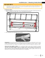
Page 33: ...rating correctly Cleaning the Outer Appliance Surface Do not use abrasive cleaners or steel wool on any painted or stainless steel parts of your Napoleon appliance Doing so will scratch the finish Ext...

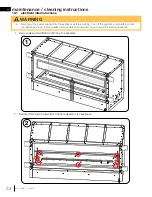
Page 34: ...power supply from the appliance before servicing Turn off the appliance completely and let cool before servicing Only a qualified service person should service and repair this electric appliance 1 Rem...

Page 35: ...g instructions 3 4 3 Lift the burner tray with the handles as illustrated Set on its side Take care not to damage pilot tube and wires 4 Remove the screw N570 0008 from the electrical box cover Remove...

Page 36: ...Install the box connection using the 7 8 22 2mm hole in the junction box 6 Connect the Green ground wire to the junction plate using the ground screw as shown Connect the common white wires together...

Page 37: ...21 37 maintenance cleaning instructions 7 7 Re install the electrical box as shown 8 Re install the burner tray with the handles as illustrated Take care not to damage pilot tube and wires 9 Re insta...

Page 38: ...y replacement parts a photocopy of the original invoice will be required to honour the claim When ordering replacement parts always give the following information Model Serial Number of appliance Inst...

Page 39: ...415 3006 A 05 27 21 39 replacement parts 11 1 overview LEGEND X STANDARD N NATURAL GAS APPLIANCES ONLY P PROPANE APPLIANCES ONLY AC ACCESSORY 20 11 5 14 7 1 2 3 4 15 9 17 8 13 6 12 18 19 16 25 26 27 2...

Page 40: ...RANSFORMER 17 LT48SS TRIM KIT 1 PER SIDE AC 18 N500 0057 JUNCTION BOX PLATE X 19 W350 0964 ELECTRICAL HOUSING 20 GSS48COV STAINLESS STEEL COVER AC 21 MKGA GLASS EMBERS AMBER 6LB MKGC GLASS EMBERS CLEA...

Page 41: ...s cleaner DO NOT CLEAN GLASS WHEN HOT If deposits are not cleaned off regularly the glass may become permanently marked Pilot will not light Makes noise with no spark at pilot burner Wiring short loos...

Page 42: ...ponents Clean using a green Scotch Brite pad to remove any contamination that may have accumulated on the sensor rod pilot hood ignitor or flame sensor Verify continuity with multimeter with ohms set...

Page 43: ...anty does not cover damages resulting from the use of components not supplied with the appliance or the use of fuel other than those specified Any damages to appliance due to weather long periods of d...

Page 44: ...oute Transcanadienne Montr al Qu bec H4T 1A3 24 Napoleon Road Barrie Ontario Canada L4M 0G8 214 Bayview Drive Barrie Ontario Canada L4N 4Y8 103 Miller Drive Crittenden Kentucky USA 41030 Phone 1 866 8...

Page 45: ...z ses instructions Si vous ne pouvez pas rejoindre votre fournisseur de gaz appelez le service des incendies Le non respect de ces instructions peut entra ner un incendie ou une explosion ce qui peut...

Page 46: ...pareils autonomes doivent tre limit s une bouteille d une capacit de 30 lb ou moins Ne pas utiliser stocker ou transporter la bouteille dans un endroit o elle serait expos e des temp ratures lev es La...

Page 47: ...ts et loin des meubles et des rideaux Les meubles ou autres objets doivent tre gard s une distance d au moins 4 pieds 1 22m du devant de l appareil Assurez vous de disposer de mesures de s curit ad qu...

Page 48: ...on devraient tre effectu es par un technicien qualifi Il est imp ratif que les compartiments de contr le le br leur et les passages de circulation d air soient gard s propres afin de fourni une combus...

Page 49: ...67 6 3 sch ma de c blage du lumi re DEL 67 6 4 installation et op ration de la t l commande 68 6 5 op ration du module de contr le 69 6 6 op ration du lumi re DEL 69 7 0 installation du gaz 70 7 1 ra...

Page 50: ...unicipalit au sujet des directives de recyclage Las bater as deben desecharse de acuerdo con las leyes y regulaciones locales Algunas bater as pueden reciclarse y es posible que su centro de reciclado...

Page 51: ...es qui s appliquent votre r gion Par exemple dans l tat du Massachusetts La soupape d arr t doit tre un robinet gaz avec une poign e en T Le raccord flexible ne doit pas mesurer plus que 36 pouces 0 9...

Page 52: ...FOR PROPANE THE GAS SUPPLY MUST BE TURNED OFF AT THE PROPANE GAS SUPPLY CYLINDER WHEN THIS APPLIANCE IS NOT IN USE DO NOT STORE OR USE GASOLINE OR OTHER FLAMMABLE VAPOURS AND LIQUIDS IN THE VICINITY...

Page 53: ...vec garniture 17 5 16 440mm 20 22 1 2 508mm 572mm 1 1 2 4 38mm 102mm VUE DE FACE sans garniture 50 1 2 1283mm 47 1 2 1207mm 16 1 2 419mm 24 1 2 622mm 3 1 2 89mm 1 8 3mm paisseur de Bord VUE DE FACE av...

Page 54: ...2 7 16 1332mm 46 7 16 1180mm 16 1 2 419mm 25 1 2 648mm 21 7 16 545 mm 1 1 2 to 4 38mm to 102mm 1 1 2 to 4 38mm to 102mm 21 1 8 537 mm 25 1 8 30 1 8 638 mm 765 mm 21 1 8 537mm 24 610mm 2 2 GSS48STE VUE...

Page 55: ...ns laquelle l appareil est utilis doit tre conforme l un des l ments suivants Installation l int rieur d une enceinte qui comporte des murs de chaque c t mais au moins une ouverture per manente au niv...

Page 56: ...une fournaise avec tube vertical 1382 F 750 C et la norme UL763 sont consid r s comme tant des mat riaux non combustibles Afin d viter un risque d incendie les d gagements minimaux aux mat riaux combu...

Page 57: ...EN ACIER 36 914 mm minimum 2 X 6 POTEAUX EN ACIER 24 3 4 629mm y compris 1 8 3mm de d gagement de chaque c t 6 152mm minimale au sol 6 152mm minimum 6 152mm minimum 1 2 13 mm PANNEAUX DE CIMENT 50 3...

Page 58: ...que c t de l appareil et fixez les la charpente d acier de 2 x 4 Les supports faciliteront l installation d une surface finie d une paisseur de 1 2 13mm ou de 3 4 19mm 4 3 d gagements aux mat riaux co...

Page 59: ...rev tement et les mat riaux de finition CERTIFI ASTM E 136 36 914mm minimum au plafond 24 3 4 629mm y compris 1 8 3mm de d gagement de chaque c t 60 3 4 1543mm minimum au plafond 6 152mm 6 152mm 6 152...

Page 60: ...When adding finishing materials to the appliance do not use wood or drywall You must have clear and easy access to the on off valve AFTER the appliance is installed and connected to the gas supply in...

Page 61: ...e appareil veillez viter les zones o une humidit excessive ou de l eau courante peut tre un probl me Pour emp cher l humidit ou l eau de s accumuler sous l appareil le constructeur doit pr voir un moy...

Page 62: ...EMENT Lors de l installation du kit de garniture en option l installateur doit laisser un espace de 5 8 po 16 mm entre le panneau de ciment et les mat riaux de finition des deux c t s pour permettre l...

Page 63: ...n en acier inoxydable Serrez en position en haut de la fente C t dentel vers le haut 1 Retirez le rev tement protecteur des pi ces de garniture avant 2 Assemblez les pi ces de garniture l aide de 8 vi...

Page 64: ...qu ce que la garniture affleure la surface avant Les supports ont t con us avec de multiples fentes incr ments de 1 4 6 mm pour s adapter diff rents mat riaux de finition 5 Desserrez la vis oreilles e...

Page 65: ...couvert par la garantie Tout le c blage doit tre effectu par un lectricien qualifi et doit tre conforme aux codes locaux En l absence de codes locaux utilisez le code lectrique canadien CSA22 1 en vi...

Page 66: ...de terre la plaque de jonction l aide de la vis de mise la terre W570 0098 l aide des connecteurs de fils connectez les fils blancs communs ensemble puis les fils noirs chauds 3 4 Non Fourni 4 R inst...

Page 67: ...CONNECTORS Digital Control Unit for LED Colour switching MD6 Connector MD6 Connector Strip Light Strip Light 6 3 sch ma de c blage du lumi re DEL TO JUNCTION BOX 110V MODULE I S FLAME SENSE IGNITER W...

Page 68: ...la couvercle de piles de l arri re de la t l commande et installez les piles A23 comme indiqu Localisez le module de contr le de l appareil Figure 10 Glissez le commutateur de la t l commande la posit...

Page 69: ...Attendez cinq 5 minutes pour que le gaz puisse s chapper Tournez soupape fermeture manuelle vers le gauche ON R glez l interrupteur du module la position ON ou REMOTE D marrez l appareil 4 R glage de...

Page 70: ...vant le premier allum age de l appareil Votre appareil peut tre converti pour utiliser du gaz propane l aide d un ensemble de conversion certifi AVERTISSEMENT Si ces instructions ne sont pas suivies l...

Page 71: ...ne conduite d alimentation en gaz propane domestique suivez les instructions pour le raccordement au gaz naturel AVERTISSEMENT Assurez vous que le robinet de la bouteille est dans sa position compl te...

Page 72: ...veau du sol et le bord sup rieur moins de 5 po 127 mm au dessus du niveau du sol Les ouvertures doivent tre de dimensions gales espac es d au moins 90 1 57 rad et non obstru es c Chaque ouverture doit...

Page 73: ...oir un r sidu d huile fin qui doit tre nettoy avant l installation Nettoyez la vitre avec du savon vaisselle doux gouttez rincez soigneusement et s chez avant l installation 1 Versez soigneusement les...

Page 74: ...le de l appareil la position ON J Si l appareil ne fonctionne pas suivre les instructions de couper l alimentation de gaz et puis appelez votre technicien de service ou fournisseur de gaz A R gler le...

Page 75: ...passages d air de circulation de l appareil soient maintenus propres N utilisez jamais l appareil lorsqu il pleut teignez toujours l appareil lorsqu il pleut Ne jamais clabousser de liquide sur le ve...

Page 76: ...lavage de votre appareil assurez vous de garder la zone autour du br leur et de la veilleuse s che en tout temps Si la commande de gaz est expos e l eau de quelque fa on que ce soit N essayez PAS d u...

Page 77: ...xt rieure de l appareil N utilisez pas de nettoyants abrasifs ou de laine d acier sur les pi ces peintes ou en acier inoxydable de votre appareil Napol on Cela gratignera la finition Les surfaces ex t...

Page 78: ...lectrique de l appareil avant de proc der l entretien teignez compl tement l appareil et laissez le refroidir avant de le r parer Seul un technicien qualifi doit entretenir et r parer cet appareil le...

Page 79: ...06 A 05 27 21 79 entretien instructions de nettoyage FR 3 Soulevez le plateau du br leur avec les poign es comme illustr 4 Retirez la vis N570 0008 du couvercle du bo tier lectrique 3 4 Electrical box...

Page 80: ...ion de la bo te en utilisant le trou de 7 8 22 2 mm dans la bo te de jonction 6 Connectez le fil de terre vert la plaque de jonction l aide de la vis de terre comme illustr Connectez les fils blancs c...

Page 81: ...tructions de nettoyage FR 7 R installez le bo tier lectrique comme indiqu 7 8 R installez le plateau du br leur l aide des poign es comme illustr Veillez ne pas endommager le tube et les fils de la ve...

Page 82: ...pi ce sous garantie une photocopie de la facture originale sera requise afin de pouvoir honorer la demande Lorsque vous commandez des pi ces donnez toujours l information suivante Mod le et num ro de...

Page 83: ...21 83 pi ces de rechange FR 11 1 vue d ensemble L GENDE X STANDARD N APPAREILS AU GAZ NATUREL UNIQUEMENT P APPAREILS AU PROPANE UNIQUEMENT AC ACCESSOIRE 20 11 5 14 7 1 2 3 4 15 9 17 8 13 6 12 18 19 1...

Page 84: ...18 N500 0057 PLAQUE DE BO TE DE JONCTION X 19 N350 0694 BO TIER LECTRIQUE 20 GSS48COV COUVERCLE EN ACIER INOXYDABLE GSS48ST UNIQUEMENT AC 21 MKGA BRAISES DE VERRE AMBRE 6LB MKGC BRAISES DE VERRE INCO...

Page 85: ...blanche ou grise se forme Le souffre du combustible se d pose sur la vitre les b ches ou les parois de la chambre de combustion Nettoyez la vitre avec un nettoyeur recommand NETTOYER PAS LORSQU ELLE E...

Page 86: ...enlever toute contamination qui ait pu s accumuler sur la tige de la sonde V rifiez la continuit avec un multim tre r gl sur Ohms au calibre le plus bas Interrupteur mural est en position off la br l...

Page 87: ...p riodes d humidit la condensation les produits chimiques ou produits d entretien nuisibles ne seront pas la responsabilit de NAPOL ON La facture ou sa copie sera requise ainsi qu un num ro de s rie e...

Page 88: ...DE CONFORT 7200 Route Transcanadienne Montr al Qu bec H4T 1A3 24 Napoleon Road Barrie Ontario Canada L4M 0G8 214 Bayview Drive Barrie Ontario Canada L4N 4Y8 103 Miller Drive Crittenden Kentucky USA 41...

Reviews: