background image

20  

EN

www.napoleongrills.com

N415-0272 DEC 20.18

BI ACCESSORY DRAWER INSTRUCTIONS

BI ACCESSORY DOOR INSTRUCTIONS

1. Unpack the drawer frame assembly.

2. Remove the drawers from the enclosure by fully extending them and then lifting up to remove them from the 

slides.

3. Shim the opening to ensure that the enclosure fits snuggly into the opening.  Ensure that the side shims are 

located at the same height as the enclosure mounting holes.  The bottom of the opening may need to be shimmed 

as well to ensure that the front of the enclosure is plumb.

4. Once the enclosure is level and square, fasten into place.  (Fasteners not included).
5. Re-install the drawers by tipping the back of the drawer down into the slide.  Once the wheels are inserted into 

the slide, lower the front of the drawer until it is level, then push in.  Note: if the enclosure is installed with shims 

that are too thick, the wheel will not engage into the slide.  The shim thickness will need to be reduced.

6. Remove the protective coating from all remaining surfaces.

1. Unpack the door and frame.

a. For the curved stainless steel doors, remove the door(s) from the frame by lifting the door while holding on to 

the pivot rod.  This will allow the pivot rod to come out of the hole on the bottom of the frame.  Once the pivot is 

removed from the bottom hole, the entire door can be dropped and removed from the frame.
b. For the PF style stainless steel door, the door needs to be removed by loosening the center philips screw on the 

hinge furthest away from the door.  This will allow the hinge to separate.

c. For double door kits N370-0502-1/N370-0503-1, refer to the instuctions included with the door kit.
2. Center the frame in the opening.  Mark the location of the pivot holes, top and bottom.  Remember on the 

PT600 double doors, there will be a pivot rod on both ends. The PF style doors do not have pivot rods.  Once all 

pivot holes are marked, remove the frame and using a 3/8” drill bit, drill out the clearance holes for the pivot rod.  

These clearance holes should be at least 1/2” deep.  After the holes are complete, you may once again center the 

frame in the opening.  Starting with the hinged side, shim between the frame and side wall of the opening.  Ensure 

the shims are close to the hinge on the PF style doors.  When the frame side wall is plumb, fasten it to the cabinet 

with screws (not provided).  Attach the other side of the frame in the same fashion, ensuring the frame is square.
3. Other than on the curved stainless steel double door kit, fasteners are not required on the top and bottom of the 

frame. The curved stainless steel double door frame must be fastened in the center both at the top and bottom.

4. Once the frame has been secured and checked for squareness, the door can be re-installed.

5. Remove the protective coating from all remaining surfaces.

BILEX605 BUILT-IN INSTRUCTIONS

N415-0272 DEC 20.18.indd   20

1/2/2019   4:03:47 PM

Summary of Contents for BILEX605

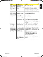
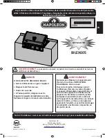
Page 1: ...or any other enclosed area WARNING CABINET FRAME CABINET AND COUNTER TOP MUST BE MADE FROM NON COMBUSTIBLE MATERIAL DO NOT DISCARD WARNING Do not try to light this appliance without reading the LIGHTI...

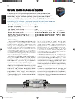
Page 2: ...ance with the installation instructions included with the product and all local and national building and fire codes has been properly maintained and has not been used as a communal amenity or in a co...

Page 3: ...any other enclosed area Natural gas units must be disconnected from the supply when being stored indoors Inspect the fuel supply hose before each use If there is evidence of excessive abrasion or wear...

Page 4: ...and lead compounds which are known to the State of California to cause cancer and chemicals including di n butyl phthalate which are known to the State of California to cause birth defects or other re...

Page 5: ...enclosure The opening must have a total free area of more than 20 in2 130 cm2 for a 20 lb 9 1 kg cylinder and 30 in2 195 cm2 for a 30 lb 13 6 kg cylinder 2 At least one ventilation opening on the exp...

Page 6: ...ponsibility of the installer and piping should be located as shown in the built in instructions A flexible metal connector is included to simplify the installation of the unit Connect this connector t...

Page 7: ...the burner lights then release 3 Press and hold igniter button until burner lights or light by match 4 If the pilot and burner will not ignite within 5 seconds turn the control knob to the off positio...

Page 8: ...l in juices first operate rear burner on high until brown then reduce the heat to thoroughly cook foods Keep the lid closed for best results Your roasts and fowl will brown perfectly on the outside an...

Page 9: ...l grilling is our most familiar choice for infrared cooking The glowing briquettes emit infrared energy to the food being cooked with very little drying effect Any juices or oils that escape from the...

Page 10: ...smoker Chicken pieces High setting 2 min each side then medium low to low setting 20 25 min The joint connecting the thigh and the leg from the skinless side should be sliced 3 4 of the way though fo...

Page 11: ...less surfaces especially the printed portion of the control panel or the printing will gradually rub off Cleaning Inside The Gas Grill Remove the cooking grids Use a brass wire brush to clean loose de...

Page 12: ...eel but extreme heat and a corrosive environment can cause surface corrosion to occur This can be removed with a brass wire brush CAUTION Beware of Spiders Spiders and insects are attracted to the sme...

Page 13: ...he ports Once a month the back burner should be fired for 5 10 minutes to burn off the accumulated grease Protection Of Infrared Burners The infrared burners of your grill are designed to provide a lo...

Page 14: ...lean burner by removing See general maintenance instructions Open air shutter slightly according to combustion air adjustment instructions This must be done by a qualified gas installer Flames lift aw...

Page 15: ...valve is turned on Turn tank on slowly to allow pressure to equalize See lighting instructions Infrared burner if equipped flashes back during operation the burner abruptly makes a loud whoosh sound...

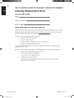
Page 16: ...is required 1 Model and serial number of the unit 2 Part number and description 3 A concise description of the problem broken is not sufficient 4 Proof of purchase photocopy of the invoice In some cas...

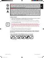
Page 17: ...issing parts please call our Customer Solutions Department at 1 866 820 8686 between 9 AM and 5 PM Eastern Standard Time CAUTION During unpacking and assembly we recommended you wear work gloves and s...

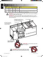
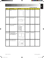
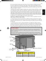
Page 18: ...T W H D 1 44mm 1 44mm BUILT IN SIDEBURNER GAS INLET OPENING NON COMBUSTIBLE MATERIAL Note Accessory frames overlap opening by 1 4cm on all 4 sides WARNING CABINET FRAME CABINET AND COUNTER TOP MUST BE...

Page 19: ...SINGLE DRAWER 17 438mm 6 171mm 23 584mm N370 0360 PF STYLE STAINLESS STEEL TRIPLE DRAWER 17 438mm 22 578mm 23 584mm N370 0502 1 N370 0503 1 DOUBLE DOOR SMALL DOUBLE DOOR LARGE FRAMES PROTRUDE FROM FA...

Page 20: ...n be dropped and removed from the frame b For the PF style stainless steel door the door needs to be removed by loosening the center philips screw on the hinge furthest away from the door This will al...

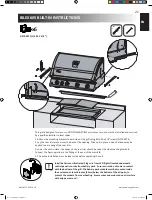
Page 21: ...wings on the rear trim should be under the side mounting brackets Connect the flex supply line to the fitting at the end of the manifold 4 The entire installation must be leak tested before operating...

Page 22: ...22 EN www napoleongrills com N415 0272 DEC 20 18 N415 0272 DEC 20 18 indd 22 1 2 2019 4 03 51 PM...

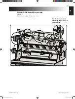
Page 23: ...com N415 0272 DEC 20 18 Rotisserie Kit Assembly Instruction optional Assemble rotisserie kit components as shown Ensure stop bushing is tightened on the inside of hood casting N415 0272 DEC 20 18 ind...

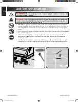
Page 24: ...performing this test and remove all sources of ignition See Leak Testing Diagram for areas to check Turn all burner controls to the off position Turn gas supply valve on 2 Brush a half and half solut...

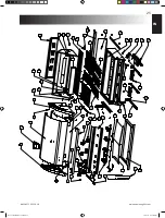
Page 25: ...272 DEC 20 18 17 3 5 4 2 1 7 10 6 20 58 50 15 40 26 12 13 14 38 25 45 31 34 33 28 52 35 36 18 41 43 42 23 24 46 16 22 9 8 11 21 53 56 27 29 44 47 55 48 49 51 54 57 30 39 39 59 16 37 32 16 N415 0272 DE...

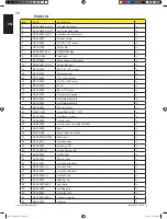
Page 26: ...x 18 N010 0544 manifold assembly p N010 0545 manifold assembly n 20 N010 0281 flex connector x 21 W445 0031 union fitting 3 8 1 2 x 22 N570 0078 m4 x 8mm screw x 23 N100 0036 main burner x 24 N080 020...

Page 27: ...orifice 51 n 52 N720 0053 rear burner supply tube x 53 N240 0024P rear burner electrode c w pilot p N240 0024N rear burner electrode c w pilot n 54 N160 0017 clip rear burner tube x 55 N080 0206 M05 r...

Page 28: ...28 EN www napoleongrills com N415 0272 DEC 20 18 Notes N415 0272 DEC 20 18 indd 28 1 2 2019 4 03 57 PM...

Page 29: ...re du gril pour consultation ult rieure NE PAS JETER AVERTISSEMENT LA CHARPENTE DU CABINET LE CABINET ET LE COMPTOIR DOIVENT TRE FAITS DE MAT RIAUX INCOMBUSTIBLES AVERTISSEMENT Ne tentez pas d allumer...

Page 30: ...ad quat tel que le sel ou le chlore des alt rations des abus des n gligences ou des pi ces install es par d autres fabricants Dans le cas d une d t rioration des composants causant le mauvais fonction...

Page 31: ...nch s de leur source d alimentation en gaz lorsqu ils sont entrepos s l int rieur Inspectez le tuyau d alimentation en gaz avant chaque utilisation S il montre des signes de fendillement excessif d us...

Page 32: ...Californie causeraient des malformations cong nitales ou autres dangers pour la reproduction Pour de plus amples renseignements visitez le www P65Warnings ca gov Sp cifications Pour La Bonbonne De Pr...

Page 33: ...erture de ventilation non obstru e sur le c t ext rieur expos de l enceinte situ e moins de 5 po 127 mm du haut du l enceinte L ouverture doit avoir un espace libre total de plus de 20 po 130 cm pour...

Page 34: ...e selon les codes locaux et ne doit pas communiquer avec la partie servant encastrer le gril Un r servoir de propane ne peut pas tre rang sous le gril AVERTISSEMENT Les grils encastr s sont munis d un...

Page 35: ...plusieurs fois 3 Appuyez et tournez lentement le bouton de contr le du br leur rotiss rie lev Ceci allumera la veilleuse qui allumera ensuite le br leur Si la veilleuse s allume continuez de garder l...

Page 36: ...liment ce qui le fait cuire lentement et de fa on gale Ce type de cuisson ressemble la cuisson dans un four et est g n ralement utilis pour les plus grosses pi ces de viande telles que les r tis les p...

Page 37: ...800 par Sir William Herschel qui fit passer la lumi re du soleil travers un prisme qui divisa la lumi re en ses composants du spectre lumineux Il d montra que la plus forte concentration de chaleur qu...

Page 38: ...de moyen bas bas 20 25 min L articulation qui retient le pilon la cuisse doit tre coup e au 3 4 partir du c t sans peau afin de permettre la viande d tre plus plat sur la grille de cuisson Ceci permet...

Page 39: ...toyez les d bris sur le br leur l aide de la brosse Nettoyez tous les d bris qui se trouvent l int rieur du gril en les faisant tomber dans le tiroir d gouttement Le tiroir d gouttement devrait tre gr...

Page 40: ...nt possiblement des probl mes d allumage Pour ajuster le volet d air 1 Enlevez les grilles de cuisson les plaques de br leur et laissez le couvercle ouvert Il sera peut tre n cessaire d ouvrir la port...

Page 41: ...a paroi arri re du gril Soulevez l arri re du br leur vers le haut pour le retirer Utilisez une brosse flexible de tube de venturi pour nettoyer l int rieur du br leur Faites sortir tous les d bris qu...

Page 42: ...eut produire suffisamment de pression pour faire fissurer la c ramique Le trempage r p t de la c ramique la fera dilater et prendre de l expansion Cette expansion causera des pressions anormales sur l...

Page 43: ...les instructions d entretien Ouvrez l g rement les volets d air tout en vous conformant aux instructions de r glage des volets d air ceci doit tre effectu par un installateur de gaz qualifi Les flamm...

Page 44: ...oir les instructions d allumage Le br leur infrarouge si quip produit des retours de flamme pendant qu il fonctionne le br leur fait subitement un bruit qui s apparente un whoosh suivi d un bruit cont...

Page 45: ...cessaire 1 Mod le et num ro de s rie de l appareil 2 Num ro de la pi ce et description 3 Description concise du probl me cass n est pas suffisant 4 Preuve d achat copie de la facture Dans certains ca...

Page 46: ...ce qui a pu laisser un r sidu pouvant tre per u comme des gratignures ou des marques Pour enlever ce r sidu frottez l acier inoxydable vigoureusement dans le sens du grain 5 Suivez toutes les instruc...

Page 47: ...LA GRILLE COMME SUPPORT R TISSOIRE W H D 1 44mm 1 44mm NOTE LE CADRE DES ACCESSOIRES CHEVAUCHE L OUVERTURE DE 1 3 4 4cm SUR LES QUATRE C T S AVERTISSEMENT LA CHARPENTE DU CABINET LE CABINET ET LE COM...

Page 48: ...LE STYLE PRESTIGE V 17 438mm 6 171mm 23 584mm N370 0360 TIROIR TRIPLE EN ACIER INOXYDABLE STYLE PRESTIGE V 17 438mm 22 578mm 23 584mm N370 0502 1 N370 0503 1 PORTE DOUBLE PETITE PORTE DOUBLE GRANDE CA...

Page 49: ...en acier inoxydable du Prestige V vous retirez la porte en desserrant la vis Philips centrale sur la charni re c est dire la vis la plus loign e de la porte Ceci permettra la charni re de se s parer...

Page 50: ...lettes de la moulure arri re doivent tre plac es sous les supports de fixation lat raux Branchez la conduite de flexible au raccord l extr mit du collecteur 4 L installation compl te doit tre v rifi e...

Page 51: ...51 FR www napoleongrills com N415 0272 DEC 20 18 N415 0272 DEC 20 18 indd 51 1 2 2019 4 04 23 PM...

Page 52: ...18 Assurez vous que la bague d arr t soit serr e l int rieur de la hotte Instructions d assemblage de l ensemble de r tissoire optionnelle Assemblez les composantes de la r tissoire tel qu illustr N4...

Page 53: ...az est remplac e ou r par e Ne fumez pas et enlevez toutes sources d allumage lorsque vous faites ce test Consultez le sch ma de test de fuites pour voir les endroits tester 2 Fermez tous les boutons...

Page 54: ...272 DEC 20 18 17 3 5 4 2 1 7 10 6 20 58 50 15 40 26 12 13 14 38 25 45 31 34 33 28 52 35 36 18 41 43 42 23 24 46 16 22 9 8 11 21 53 56 27 29 44 47 55 48 49 51 54 57 30 39 39 59 16 37 32 16 N415 0272 DE...

Page 55: ...emblage du collecteur p N010 0545 assemblage du collecteur n 20 N010 0281 connecteur flexible du collecteur x 21 W445 0031 raccord fitting 3 8 1 2 x 22 N570 0078 vis M4 x 8 mm x 23 N100 0036 br leur p...

Page 56: ...eur arri re 51 n 52 N720 0053 br leur arri re approvisionment x 53 N240 0024P lectrode du br leur arri re p N240 0024N lectrode du br leur arri re n 54 N160 0017 clip de bruleur arriere x 55 N080 0206...

Page 57: ...57 FR www napoleongrills com N415 0272 DEC 20 18 Notes N415 0272 DEC 20 18 indd 57 1 2 2019 4 04 28 PM...

Page 58: ...58 FR www napoleongrills com N415 0272 DEC 20 18 Notes N415 0272 DEC 20 18 indd 58 1 2 2019 4 04 28 PM...

Page 59: ...59 FR www napoleongrills com N415 0272 DEC 20 18 Notes N415 0272 DEC 20 18 indd 59 1 2 2019 4 04 28 PM...

Page 60: ...N415 0272 N415 0272 DEC 20 18 indd 60 1 2 2019 4 04 29 PM...

Reviews: