background image

EN

W415-1285 / J / 11.15.19

27


venting installation

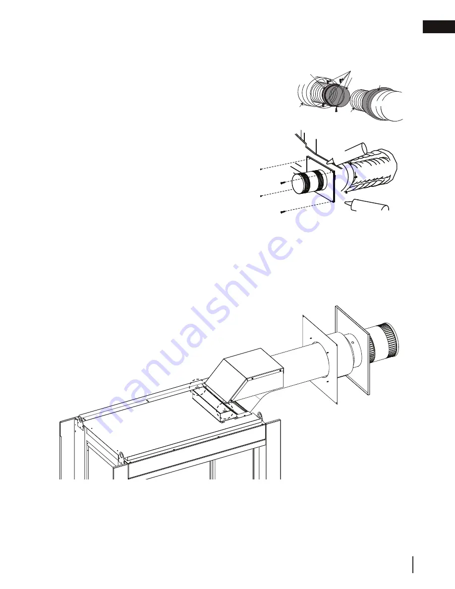
5.3.1  horizontal air terminal installation

A. 

Stretch the inner fl ex pipe to the required length taking 
into account the additional length needed for the fi nished 
wall surface. Apply a heavy bead of the red RTV silicone 
(W573-0002) (not supplied) to the inner sleeve of the air 
terminal. Slip the vent pipe a minimum of 2” (50.8mm) 
over the inner sleeve of the air terminal and secure with a 
minimum of 3 screws. 

B. 

Using the outer fl ex pipe, slide over the outer combustion 
air sleeve of the air terminal and secure with a minimum 
of 3 screws. Seal using red RTV silicone (W573-0002) 
(not supplied).

C. 

Insert the vent pipes through the fi restop maintaining 
the required clearance to combustibles. Holding the air 
terminal (lettering in an upright, readable position), secure 
to the exterior wall and make weather tight by sealing 
with caulking (not supplied).

D. 

If more vent pipe needs to be used to reach the fi replace, 
couple them together, as illustrated. The vent system 
must be supported approximately every 3 feet (0.9m) for 
both vertical and horizontal runs. Use non-combustible 
strapping to maintain the minimum clearance to 
combustibles.  

E. 

Stove Appliances Only:

 From inside the house, using 

Red RTV Silicone (W573-0002) (not supplied), seal 
between the vent pipe and the fi restop. Then slide the black trim collar over the vent pipe up to the 
fi restop.

The air terminal mounting plate may be recessed into the exterior wall or siding no greater than the 
depth of its return fl ange.

ADD FASTENER TYPE

ADD GRAPHIC

Screws

(Supplied)

2" (50.8mm) Overlap

Outer Flex Pipe

Inner Flex

    Pipe

Caulking

Red RTV Silicone

Screws

Inner Coupler

Outer Coupler

Outer Flex 

Pipe

Inner Flex 
Pipe

Outer Flex 

Pipe

Red RTV Silicone

E. 

The vent shield must be installed only when terminating horizontally. Remove the two screws nearest  


the vent collars on the top of the appliance. Align the vent heat shield (supplied) and secure. Adjust    


the vent heat shield to touch the fi restop spacer, as shown below.

Summary of Contents for Ascent Multi-View Series

Page 1: ...as supplier from a neighbour s phone Follow the gas supplier s instructions If you cannot reach your gas supplier call the re department Installation and service must be performed by a quali ed instal...

Page 2: ...burns A physical barrier is recommended if there are at risk individuals in the house To restrict access to an appliance or stove install an adjustable safety gate to keep toddlers young children and...

Page 3: ...anemia those under the in uence of alcohol those at high altitudes are more affected by carbon monoxide than others Failure to keep the primary air opening s of the burner s clean may result in sooti...

Page 4: ...ion 33 9 0 operation 34 9 1 pilot on demand 35 10 0 operating instructions 36 10 1 operating instructions for your safety read before operating 36 10 2 lighting instructions 36 11 0 finishing 37 11 1...

Page 5: ...ddress Date of Installation Location of appliance Installer Dealer Distributor contact number Serial Model Natural Gas BHD4PN BHD4STN BHD4PGN BHD4STGN BHD4PFCN BHD4STFCN Propane BHD4PP BHD4STP BHD4PGP...

Page 6: ...not convertible for use with other gases unless a certi ed kit is used The protective wrap on plated parts is best removed when the assembly is at room temperature but this can be improved if the asse...

Page 7: ...ed combustion product The installation must conform with local codes or in absence of local codes the National Gas and Propane Installation Code CSA B149 1 in Canada or the National Fuel Gas Code ANSI...

Page 8: ...LIANCE NOT FOR USE WITH SOLID FUEL APPAREIL GAZ D CORATIF VACUATION N EST PAS UNE SOURCE DE CHALEUR N EST PAS DESTIN TRE UTILIS COMME UN APPAREIL DE CHAUFFAGE NE CONVIENT PAS AUX COMBUSTIBLES SOLIDES...

Page 9: ...03mm 5 127mm 1213 16 325mm 251 8 638mm RIGHT SIDE LEFT SIDE RIGHT SIDE LEFT SIDE 79 16 192mm ELECTRICALINLET 79 16 192mm GAS INLET 21 16 53mm 343 16 868mm 45 1143mm 381 4 841mm 79 16 192mm ELECTRICALI...

Page 10: ...ded for the initial installation This appliance must be installed with a continuous connection of exhaust and air intake vent pipes Utilizing alternate constructions such as a chimney as part of the v...

Page 11: ...r of elbows to a minimum The air terminal must remain unobstructed at all times Examine the air terminal at least once a year to verify that it is unobstructed and undamaged Rigid and exible venting s...

Page 12: ...equired the appliance must have a minimum vertical rise off the appliance of 57 144 8cm On all horizontal vent runs ensure that the vent pipe does not slope downward When terminating vertically the ve...

Page 13: ...e vent length is 10 3 1m for a replace and 8 2 4m for a stove 38 1 4 97 2cm 24 61cm MIN REGARDLESS OF HORIZONTAL VENT LENGTH 12 30 5cm MIN TO GRADE 3 2 2 reduced vent clearance to combustibles The min...

Page 14: ...pter to the appliance collars X3 X3 5 6 3 3 converting from 5 8 to 4 7 venting Use Mill Pac to seal adapter to the appliance collars Use red RTV silicone sealant to seal adapter to the appliance colla...

Page 15: ...ch or deck N 16 40 6cm 16 40 6cm Clearance above the roof O 2 0 6m 2 0 6m Clearance from an adjacent wall including neighbouring buildings P 8 2 4m 8 2 4m Roof must be non combustible without openings...

Page 16: ...ical rise to maximum of 40 feet 12 2m Horizontal run vertical rise to maximum of 40 feet 12 2m Vertical Termination For the following symbols used in the venting calculations and examples are greater...

Page 17: ...nt con gurations requiring more than two 90 elbows the following formulas apply Formula 1 HT VT Formula 2 HT VT 40 feet 12 2m Example V1 8 FT 2 4m VT V1 8 FT 2 4m H1 2 5 FT 0 8m H2 2 FT 0 6m HR H1 H2...

Page 18: ...24 75 feet 7 5m Example V1 4 FT 1 2m V2 1 5 FT 0 5m VT V1 V2 4FT 1 2m 1 5FT 0 5m 5 5 FT 1 7m H1 2 FT 0 6m H2 1 FT 0 3m H3 1 FT 0 3m H4 1 5 FT 0 5m HR H1 H2 H3 H4 2FT 0 6m 1FT 0 3m 1FT 0 3m 1 5FT 0 5m...

Page 19: ...T 40 feet 12 2m Example V1 5 FT 1 5m V2 10 FT 3 1m VT V1 V2 5 FT 1 5m 10 FT 3 1m 15 FT 4 6m H1 3 FT 0 9m H2 2 5 FT 0 8m HR H1 H2 3FT 0 9m 2 5FT 0 8m 5 5 FT 1 7m HO 03 one 45 three 90 elbows 135 03 45...

Page 20: ...3 45 270 135 5 4 FT 1 6m HT HR HO 8FT 2 4m 5 4FT 1 6m 13 4FT 4 1m HT VT 13 4FT 4 1m 2 5FT 0 8m 15 9FT 4 8m Formula 1 HT 3VT 3VT 3FT 0 9m x 2 5FT 0 8m 7 5FT 2 3m 13 4 FT 4 1m 7 5 FT 2 3m Since this for...

Page 21: ...ce may cause over heating and re Prevent contact with sagging or loose insulation or framing and other combustible materials Block opening into the chase to prevent entry of blown in insulation Make s...

Page 22: ...22 1 8 56 2cm MAX 24 1 8 61 3cm B MIN 42 1 2 108cm MAX 43 1 2 110 5cm 4 1 framing 4 1 1 see thru framing BHD4ST 4 1 2 peninsula framing BHD4P All framing dimensions are based on the nishing material...

Page 23: ...7cm minimum enclosure 4 2 minimum clearance to combustible enclosures 4 2 1 see thru BHD4ST 4 2 2 peninsula BHD4P Within the appliance enclosure a minimum 3 76mm clearance between the top of the vent...

Page 24: ...igid vent components a minimum of 3 screws must also be used to ensure the connection cannot slip off Do not clamp the exible vent pipe Risk of re explosion or asphyxiation Improper support of the ent...

Page 25: ...h a roof Installation kits for various roof pitches are available from your authorized dealer distributor See the accessories section to order speci c kits required A Determine the air terminal locati...

Page 26: ...supplied However the high temperature sealant W573 0007 Mill Pac not supplied must be used on the joint connecting the inner ex pipe and the exhaust ue collar Use only approved exible vent pipe kits m...

Page 27: ...e vent pipe needs to be used to reach the replace couple them together as illustrated The vent system must be supported approximately every 3 feet 0 9m for both vertical and horizontal runs Use non co...

Page 28: ...iving a 3 4 19mm margin all around Fasten to the roof Do not nail through the lower portion of the ashing Make weather tight by sealing with caulking Where possible cover the sides and top edges of th...

Page 29: ...and shall be in compliance with local codes In the absence of local codes use the current CSA22 1 Canadian Electric Code in Canada or the current National Electric Code ANSI NFPA NO 70 in the United S...

Page 30: ...ews This will allow you to easily access the battery housing C Remove your battery housing to install the batteries this will be located in the control compartment as shown below D Install the four AA...

Page 31: ...IN SERIES WITH EITHER THE EXISTING SWITCH OR OPTIONAL WALL SWITCH THERMOSTAT OR REMOTE Do not wire 110 volts to the valve or wall switch WARNING This appliance comes equipped with a battery back up If...

Page 32: ...lve Disconnect gas supply piping before testing gas line at test pressures above 1 2 PSIG Valve settings have been factory set do not change Installation and servicing to be done by a quali ed install...

Page 33: ...cation and where to bend the nailing tabs you must rst determine the thickness of your nishing material i e drywall This will determine the dimension from the front edge of the corner post to the nail...

Page 34: ...e wall switch to the appliance J If the appliance will not operate follow instructions TO TURN OFF GAS and call your service technician or gas supplier A Set thermostat to lowest setting if equipped B...

Page 35: ...en begin the countdown for approximately seven days before shutting off the pilot if the appliance is not used This countdown will reset anytime the appliance main burner is used Therefore if the appl...

Page 36: ...IAL LIGHTING OF THE PILOT AND MAIN BURNERS MUST BE DONE WITH THE GLASS DOOR OFF DO NOT CONNECT VALVE OR WALL SWITCH TO ELECTRICITY SEE INSTALLATION INSTRUCTIONS A THIS APPLIANCE IS EQUIPPED WITH AN IG...

Page 37: ...safety barrier removal installation WARNING Risk of re Never obstruct the front opening of the appliance The front of the appliance must be nished with any non combustible materials such as brick marb...

Page 38: ...curing screws from the top and bottom of the end screen retainer refer to Figure 1 B Pull the safety screen forward and out from the appliance refer to Figure 2 FIG 1 FIG 2 One of the main safety barr...

Page 39: ...ottom door retainer E Reverse this process to install the door LATCHES FIG 1 FIG 2 11 4 main door removal installation IMPORTANT Once latches are engaged test that the door is secure and will not fall...

Page 40: ...steps 6 screws PANEL COVER CONTROL PANEL COVER 11 6 control panel removal A Remove the main safety screen see main safety barrier removal installation section B Remove the panel cover using the two n...

Page 41: ...the appliance If grout is used between the tiles a polymer based grout such as Mapei Ultracolour plus is recommended Primer Paint For a painted surface use a 100 acrylic latex primer and nish coat Pa...

Page 42: ...the 8 screws on each nishing support Adjust the nishing support to the desired position SIDE VIEW B A 1 2 13mm MIN 1 1 2 38mm MAX 11 7 1 nishing support adjustment Peninsula models have one end suppo...

Page 43: ...EPTH 12 10 8 6 4 2 1 3 4 5 6 7 8 9 10 A B C D 38 1 4 97 2cm TOP OF APPLIANCE 11 8 minimum mantel clearances WARNING Risk of re Maintain all speci ed air space clearances to combustibles Failure to com...

Page 44: ...desired increase the clearance to the sides bottom and top by 2 50 8mm for every additional 1 25 4mm of projection If using an optional surround the same rule applies starting from the top of the sur...

Page 45: ...installation and main door removal installation sections for removal instructions 2 Place a pin into the bottom of log 1 lining it up with the hole in the hearth pad Then place onto the screw and spa...

Page 46: ...nto log 7 FIG 9 11 Place log 10 onto the pin located in log 7 and let it rest in the middle of the right side hearth pad as shown in Figure 10 Place one pin into log 1 FIG 10 12 Place log 11 onto the...

Page 47: ...tely blocking the burner ports can cause an incorrect ame pattern carbon deposits and delayed ignition Randomly place the charcoal embers along the front and sides of the log support in a realistic ma...

Page 48: ...lite in or around the pilot opening and or on the burner ports This will interfere with the pilot operation Evenly spread the glass media onto the media tray covering the burner tube and tray Ensure n...

Page 49: ...EN W415 1285 J 11 15 19 49 nishing LOGO 1 2 13mm 1 2 13mm 11 13 logo placement...

Page 50: ...inlet pressure not to exceed 13 Pressure Natural Gas inches Natural Gas millibars Propane inches Propane millibars Inlet 7 minimum 4 5 17 4mb minimum 11 2mb 13 minimum 11 32 4mb minimum 27 4mb Outlet...

Page 51: ...ot and burner ames Compare them to the illustration provided If any ames appear abnormal call a service person ADD IMAGE HERE 12 4 ame characteristics GLASS BURNER LOG BURNER CRADLE FLAME MUST ENVELOP...

Page 52: ...ner 5 If your appliance is equipped with a safety barrier cleaning may be necessary due to excessive lint dust from carpeting pets etc simply vacuum using the brush attachment 6 If your appliance is e...

Page 53: ...sult in a discoloured stain or scratch like mark More importantly this can scratch the glass surface thereby reducing its strength Do not operate the appliance with broken glass as leakage of ue gases...

Page 54: ...re they open freely and close sealed Check the gas control valve pilot and Hi Lo knobs move freely if equipped Replace if any stiffness in movement is experienced Check for gas leaks on all gas connec...

Page 55: ...burner removal 13 4 1 log burner removal A Remove the main door s from the appliance see main door removal installation section B Vacuum the glass media out of the appliance Ensure you insert a clean...

Page 56: ...MEDIA BOWL SUPPORT D 13 4 3 cradle burner removal A Remove the safety screen and main door s See main safety barrier removal installation and main door removal installation sections for detailed remo...

Page 57: ...ts can be ordered through your Authorized dealer distributor For warranty replacement parts a photocopy of the original invoice will be required to honour the claim When ordering replacement parts alw...

Page 58: ...screen Safety screen W010 2898 W100 0161 SER Log cradle burner assembly W010 3207 Log cradle burner valve train assembly W010 3206 Glass burner valve train assembly W100 0160 Glass burner assembly Yes...

Page 59: ...686 W710 0059 SER Glass media tray W010 3481 Media bowl assembly W010 2997 Media bowl trim assembly W080 1395 ACS switch bracket W750 0191 ACS switch W707 0010 Transformer W010 2829 Door latch assemb...

Page 60: ...14 3 glass burner assembly 2 4 3 1 2 4 3 1 Ref No Part number Description 1 W010 2954 SER Burner assembly 2 W080 1400 SER Burner bracket 3 W290 0018 Venturi gasket 4 W720 0005 Venturi Stocked Yes Ite...

Page 61: ...ked Yes Items may not appear exactly as illustrated 5 5 13 15 13 16 3 W290 0157 Manifold gasket 4 W105 0001 Bushing 5 6 7 Yes 8 W010 1985 Wire harness assembly W190 0175 Control board W080 1366 Valve...

Page 62: ...4 3 1 5 2 4 3 1 5 Ref No Part number Description 1 W010 2955 Burner assembly 2 W080 1463 Burner bracket 3 W290 0018 Venturi gasket 4 W720 0005 Venturi 5 W080 1399 Burner bracket Stocked Yes Ref No Pa...

Page 63: ...ng 9 W010 3024 Pilot assembly NG 10 Stocked Yes Stocked Yes 6 5 13 12 16 15 Yes W080 1372 Pilot bracket 11 W035 0338 Valve train base 12 W200 0456 Valve access cover 13 W290 0247 Access gasket Yes 15...

Page 64: ...d Media Kit Various colors MKB_ Glass Embers Media Kit Various colors GD851KT PRPHD4 10 3 19 20 21 Yes 9 22 4 MRKM Mineral rock kit PRPHD4 Porcelain Re ective Radiant Panel End 5 GD851KT Decorative Br...

Page 65: ...E Leak test with a soap and water solution Air shutter improperly adjusted Return air shutter to speci ed opening see venturi adjustments section in the installation manual Carbon is being deposited o...

Page 66: ...eiver if equipped Reset program hold reset button on receiver and wait for 2 beeps Release after second beep Press small ame button on remote within 20 seconds you will hear an additional beep this si...

Page 67: ...e one of the 3 methods below to reset the system 1 To reset ignition box when locked out Turn off power supply and remove batteries if used from the back up battery pack 2 To reset the DFC Board when...

Page 68: ...t be caused by mechanical systems such as exhaust fans furnaces clothes dryers etc Any damages to the appliance combustion chamber heat exchanger plated trim or other components due to water weather d...

Page 69: ...J 11 15 19 69 service history 18 0 service history Appliance Service History This appliance must be serviced annually depending on usage Date Dealer Name Service Technician Name Service Performed Spec...

Page 70: ...TI IN NG G O OV VE ER R 4 40 0 Y YE EA AR RS S A A A O O O O O OF F F F F F H H H H H H H HO O O O O OM M M M ME E E E E C C CO OM M MF F FO OR RT T P PR RO OD DU UC CT TS S 7200 Route Transcanadienne...

Reviews: