


NAPCO StarLink Fire: Getting Started Guide
13
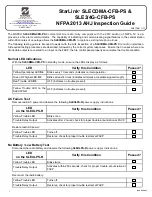
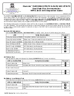
The following summarizes the minimum required NOC programming (
h
Ʃ
p://NapcoNOC.com
) and system wiring when connec
Ɵ
ng a StarLink Fire Communica-
tor to the DACT of an FACP, u
Ɵ
lizing dial capture mode repor
Ɵ
ng. Check the installa
Ɵ
on and programming instruc
Ɵ
ons for addi
Ɵ
onal wiring and programming
op
Ɵ
ons. Be sure all items in the following checklist are performed:
1.
Central Sta
Ɵ
on Receiver Telephone numbers are programmed in the "
Dealer
Entered
Programming
" sec
Ɵ
on (see image at right):
2.
UL
Poll
Fail
Timeout
is set (200 seconds NFPA 2007 service plan; 5 min. for
NFPA 2010 plan; 60 min. for NFPA 2013 plan or 24hr backup only):
3.
(
PGM1
) is wired to a trouble zone in the FACP. Wire the control panel Listed
EOLR in series (terminal 3 PGM Output #1 and ground terminal #8) to a zone or
point programmed to monitor communicator troubles.
Installation Quick Start / Checklist for Fire Alarm Control Panel DACT Connect Operation
WI2162A 04/16
6
7
8
15
14
13
12
11
9 10
2
3
4 5
1
17
16
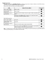
StarLink Terminals
(STARLINK HOUSING)
All connections are power limited except AC Mains,
Telco and battery terminals.
Terminals 14-17: No connections permitted.
RED
GREEN
9LE10KHARN installed in FACP:
Blue/Red normally closed relay open on trouble
Red/Black normally open relay short on alarm
To FACP Ground /
Common Terminal
(not earth ground)
To panel Telco if using
DACT reporting
+V
(12/24V)
(
–
) PGM1
PGM2
PGM3 IN1 IN2 GND IN3
RING
TIP
RTS
(R)
PANEL
TX (B)
PANEL
RX (G)
CTS
Y
PANEL
RING (+)
PANEL
TIP (–)
(Use FACP Listed
EOLR)
To FACP conventional
zone positive terminal
programmed for
communicator trouble
See
Note 3
If using addressable input for
communicator supervision,
connect Form C relay as
shown below.
–
+
EOLR
EOLR
C
N/C
N/O
See
Note 4
2
1
Note: All wiring diagrams and programming depicted in this guide assume the wiring between the radio and the FACP is protected by conduit.
Notes:
1. For NAPCO control panel downloading or
remote
upgrading
of
radio
fi
rmware
, radio jumper
X5_J1
must be removed.
2. Upon ac
Ɵ
va
Ɵ
on of the
fi
re trouble relay (open between blue and red harness wires), a
fi
re trouble signal will be transmi
Ʃ
ed to the central sta
Ɵ
on.
3. For StarLink models SLECDMA-CFB-PS and SLE3/4G-CFB-PS, connect to charger board terminal labeled
N/O
.
4. If using external relay for radio supervision, relay must be rated for radio input voltage, (12VDC, max current draw=50mA OR 24VDC, max current
draw=25mA). A listed low current relay, such as
Space Age Electronics
model SSU-MR-311/C/R is recommended.
Summary of Contents for StarLink Connect Series
Page 2: ...2 NAPCO StarLink Fire Getting Started Guide...
Page 4: ...4 NAPCO StarLink Fire Getting Started Guide...
Page 5: ...NAPCO StarLink Fire Getting Started Guide 5...
Page 6: ...6 NAPCO StarLink Fire Getting Started Guide...
Page 7: ...NAPCO StarLink Fire Getting Started Guide 7...
Page 8: ...8 NAPCO StarLink Fire Getting Started Guide...
Page 12: ...12 NAPCO StarLink Fire Getting Started Guide...
Page 26: ...26 NAPCO StarLink Fire Getting Started Guide...
Page 30: ...30 NAPCO StarLink Fire Getting Started Guide...
Page 34: ...34 NAPCO StarLink Fire Getting Started Guide...


