background image

27

                                          Accelaterm 

® 

Installation and Service Manual


Functions of the ‘485 Data Pair Connections 


Note:

  A (+) is always connected to a (+), and a (-) always to a 

(-).  A Transmitter is always connected to a Receiver.  

Up-

stream cables head toward the Server; downstream cables head 
away from the Server. 

T+ 

T- 

Differential  
Transmitter Data 


R+ 

R- 

Differential  
Receive Data 


Example – Accelaterm Ethernet to ‘485 Repeater Network 

ADDRESS

 = 01

*


Ethernet 

and

 ‘485 

Interfaces Installed. 
Bridge 

[

††

]

†

 STD 

ADDRESS

 = 02

*


‘485 Repeater 
Interface Installed. 
Bridge 

†

[

††

]

 STD 

ADDRESS

 = 03

*


‘485 Repeater 
Interface Installed. 
Bridge 

†

[

††

]

 STD 

ADDRESS

 = 04

*


‘485 Repeater 
Interface Installed. 
Bridge 

†

[

††

]

 STD 

ADDRESS

 = 05

*


‘485 Repeater 
Interface Installed. 
Bridge 

†

[

††

]

 STD 

T+ 

T- 

R+ 

R- 

R+ 
R- 
T+ 
T- 


T+ 

T- 

R+ 

R- 

R+ 
R- 
T+ 
T- 


T+ 

T- 

R+ 

R- 

R+ 
R- 
T+ 
T- 


T+ 

T- 

R+ 

R- 

R+ 
R- 
T+ 
T- 


If last unit, Downstream 
Connections  
left open. 

UL294A compliant installation requires UL497B-Listed Surge arrestors be installed on all data lines connected to Computer Ac-
cessory Equipment.  On the downstream side, Ground Loop currents are limited by the low-capacitance, high-voltage disc capaci-
tor.  This connection assures compatibility with nearby Radio-Frequency equipment. 
“Ethernet Only” installations may use third-party isolated USB to 485 Convertors connected to the Upstream side of the first Ac-
celaterm panel. Contact Continental Tech Support for latest data. 
*

Note:

  Address of the Accelaterm are not required to be consecutive, only that the Bridge Accelaterm be first. 

Host 
Computer 
or Server 

UL497B 
Surge 
Arrestor 

T+ 

T- 

R+ 

R- 

_    _ 


T+ 

T- 

R+ 

R- 

3KV 

T+ 

T- 

R+ 

R- 

_    _ 


T+ 

T- 

R+ 

R- 

Drain Wire connected to 
Cabinet Ground Post 

Bridge 

OUT 

STD 

OUT 

STD 

IN 

STD 

OUT 

STD 

OUT 

STD 

IN 

STD 

IN 

STD 

IN 

Bridge 

Out 

STD 

Out 

STD 

In 

T+ 

T- 

R+ 

R- 

_    _ 


T+ 

T- 

R+ 

R- 

Drain Wire connected to 
Cabinet Ground Post 

STD 

Out 

STD 

In 

COMMUNICATION CONNECTIONS 

Figure 19 - Accelaterm Ethernet to ‘485 Repeater Network 

Summary of Contents for Continental Access Accelaterm

Page 1: ...Sixteen Door Access Control Panel Installation and Service Manual A NAPCO SECURITY GROUP COMPANY 355 Bayview Avenue Amityville NY 11701 Phone 631 842 9400 Fax 631 842 9135 www cicaccess com Publicly...

Page 2: ...Information furnished by Continental Access is believed to be accurate and reliable However no responsibility is assumed by Continental Access for its use nor for any infringements of other rights of...

Page 3: ...the limits for a Class A computing device pursuant to Part 15 of FCC Rules which are de signed to provide reasonable protection against such interference when operated in a commer cial environment Ope...

Page 4: ...CTIONS 22 ACCESSORY POWER 23 ACCESSORY ALARM CONNECTIONS 24 Supervised Alarms 24 Configuring an Alarm in the Supervised Condition 25 Tamper Switch 24 COMMUNICATION 25 Networking 26 485 Repeater Networ...

Page 5: ...n a replaceable lithium battery protects the on board database and programmed operating instructions from loss for a period of 4 weeks In the event of a total failure of the AC power supply and the ba...

Page 6: ...pair cable Where the AHJ s Authorities Having Jurisdiction require Plenum Rated Cabling UL Type CL2P cabling may be acceptable All external wiring must be UL Listed suitable for the installation appli...

Page 7: ...BRIDGE allows the Host Computer to communicate with several panels on a full duplex EIA TIA 485 Repeater Chain through the primary Accelaterm Memory The Base Processor Memory Board of the Accelaterm...

Page 8: ...ware supervises the Access Control System reporting failures at an individual panel within seconds of the occurrence Nevertheless failures can occur at the Door Sense and Bypass contact monitoring har...

Page 9: ...ists on both sides of the Accelaterm cabinet for cabling conduit entering and exiting the cabinet Determine the directions of the cabling conduit exiting the Accelaterm cabinet Confirm sufficient acce...

Page 10: ...nd B 3 Place the Accelaterm cabinet out of the way 4 Drill pilot holes to the required depth and size for the mounting screws 5 Insert the top two mounting screws into the wall Leave approximately one...

Page 11: ...nduit Knockout The Accelaterm System requires 120VAC 2A 60Hz or 230VAC 1A 50Hz voltage to the AC Input Power Terminal Block see page 12 The power cabling is delivered to the Accelaterm through a knock...

Page 12: ...ired IMPORTANT SAFETY REQUIREMENT If the enclosure door is removed the Ground Strap may be unbolted but MUST be REATTACHED after installation or service is completed Failure to Reconnect the Ground St...

Page 13: ...g for auxil iary power ACC PWR OUT wiring as noted in the above image Figure 7 Power Limited Wiring Information POWER CONNECTIONS Neutral Connection to branch circuit Class 1 Wiring Connection Power L...

Page 14: ...rcuit board shown below and use cutaway drawings to identify specific locations on the circuit board WIRING DIAGRAM Figure 8 Accelaterm Interface Circuit Board Layout Replaceable Memory Cell Holder I2...

Page 15: ...wires and cable shields at any other point Keypad Connection Wiegand Output Card and Keypad Readers The preferred connection for Card and Keypad installations is the use of a UL Listed Wiegand Output...

Page 16: ...GND LED D1 D0 DS RT REX RT DOOR CONNECTIONS Figure 9 Wiegand Proximity Reader Connection to Accelaterm Board Accelaterm Circuit Board Wiegand Proximity Reader Terminal Strip Red Black Brown White Gree...

Page 17: ...e Readers short Connect drain wires to the ground posts located on both sides of Accelaterm cabinet DO NOT ground drain wires and cable shields at any other point DOOR CONNECTIONS Table 6 Connection T...

Page 18: ...losed It also senses if the door was forced open triggers a Door Forced Alert at the Host Computer at the central station DOOR CONNECTIONS CAUTION Keep all drain wires short Connect drain wires to the...

Page 19: ...operation of the Accelaterm and the Request to Exit sensor DOOR CONNECTIONS Table 10 Connection Table for Request to Exit Sensor DRx Terminal Strip Pin Signal REX Alarm Positive RT Return Negative Re...

Page 20: ...e connected to JP4 LOCK PWR IN 5 8 and 13 16 at the bottom right of the Relay Board not evaluated by UL A Field Wiring Acces sory Cable Assembly is available from Continental part num ber 9CICP2800AUX...

Page 21: ...s 2A The configuration jumpers are set to D for Dry contact output Lock 3 A fail safe EM Lock powered by the Accelaterm s internal battery backed 12VDC power Maximum recom mended lock current rating i...

Page 22: ...ot evaluated by UL A 9CICP2800AUXH Accessory Cable provides two pairs of conductors for two power limited circuits The power supply may be one or two UL603 or UL294 listed units Normally battery backe...

Page 23: ...located in the lower middle of the Relay Board Table 12 lists the ACC PWR OUT terminal strip pin numbers and their associated functions Note 12VDC current draw is limited to a total maximum of 75 Amp...

Page 24: ...two 1K Ohm 1 4W 5 carbon film resistors per alarm 2 Install R 1 in parallel with the alarm contacts see Figure 15 3 Install R2 in series with the alarm input conductor Note For maximum protection ins...

Page 25: ...d CICP2800RS485BD board allows di rect connection with other Access Control Panels upstream and downstream on a 4 wire Repeater String This allows for high data rates and industry leading isolation fr...

Page 26: ...re set with a small screwdriver There is a click detent for each number The valid address range is 01 to 63 Address 00 is not valid See Clear Memory and Force Download to Panel on page 31 Communicatio...

Page 27: ...nt installation requires UL497B Listed Surge arrestors be installed on all data lines connected to Computer Ac cessory Equipment On the downstream side Ground Loop currents are limited by the low capa...

Page 28: ...lled by test firmware during development ETH RX Ethernet Receive Data Ethernet Port is receiving data from the Host Computer ETH TX Ethernet Transmit Data Ethernet Port is transmitting data to the Hos...

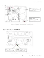
Page 29: ...ackup Battery PWR 12 Volt DC Into board from Power Supply Does not light if operating on Backup Battery Processor Memory Board CICP2800PMBD RST Red Reset Steady Blink indicates trouble PWR 5 Volt DC P...

Page 30: ...fe of the relay contacts Dielectric Isolation The Ethernet Port meets the IEEE 802 3 Specification Stan dard for 1500V RMS Dielectric Isolation Dielectric Isolation is the appropriate technology becau...

Page 31: ...dle the cell by its edge to avoid contaminating the conductive surfaces 5 The expected life of the lithium cell is ten years Chang ing the battery every five years is recommended Note The coin cells a...

Page 32: ...ay Expansion 48 using External I O Expansion Units Supervised Inputs Alarm Door Sense Bypass Door Sense Bypass Eight Sixteen Sixteen All inputs Host configurable as dry contact Base Interface Board Wi...

Page 33: ...Standard Facility Codes 10 Standard Transaction Buffer 1000 Standard configurable and expandable Cables AWG Type Maximum Length Alarm Inputs 22 Stranded shielded w drain 2 conductor 500 ft 153m Reader...

Page 34: ...ach energized relay board relay Expansion Board 20mA Interface Board Repeater Module 20mA Ethernet Board 120mA Interface Board and Expansion Board Output Ratings Interface Board and Expansion Board re...

Page 35: ...t cable first through a cable clamp Fig 13 and then through a knockout located on the right side of the panel enclosure Pull only enough of the Ethernet cable into the en closure to allow the plug to...

Page 36: ...on and off once per second Also verify the heartbeat lamp on the motherboard location T1 blinks in unison with the OK lamp on the Interface board Note The status LEDs on the top of the Ethernet board...

Page 37: ...5V power for special readers and accessory equipment The 5V power is highly filtered and separate from the logic power Each of the 8 alarm inputs on the main board may be config ured as supervised al...

Page 38: ...d wiring can be greatly simplified by routing the lock power through the Accelaterm Relay Board To the right of the center line on the Relay Board find JP4 marked LOCK PWR IN 5 8 and 13 16 A 9CICP2800...

Page 39: ...mit are wired to the first downstream Accelaterm top four terminals respectively STD Transmit STD Transmit STD Receive STD Receive All non Bridge CICP2800RS485BD s are wired to the upstream CICP2800RS...

Page 40: ...y that the Accelaterm control panel is working correctly 2 Disconnect power to the system including the battery wires 3 Install Standoffs The Repeater board is mounted in the top right corner of the A...

Page 41: ...41 Accelaterm Installation and Service Manual NOTES...

Page 42: ...s financial capabilities Continental will charge a Service Fee of 50 00 for any returned check If customer believes an invoice to be in error cus tomer shall notify Continental of the error within th...

Page 43: ...any indirect consequential or incidental damages in cluding those to person and those for lost wages or other economic loss Product Liability Continental s sole Liability and the customer s exclu sive...

Page 44: ...laterm Installation and Service Manual 44 A NAPCO SECURITY GROUP COMPANY 355 Bayview Avenue Amityville NY 11701 Phone 631 842 9400 Fax 631 842 9135 www cicaccess com Publicly traded on NASDAQ Symbol N...

Reviews: