Accelaterm
®
Installation and Service Manual
24
Drain Wire/
Shield
ACCESSORY ALARM CONNECTIONS
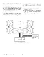
Eight accessory supervised alarm inputs are located on the
Accessory ALARM terminal strip located on the upper left
corner of the Accelaterm circuit board (see Figure 15). These
alarm inputs may be used for dry contact type inputs
(unsupervised) or supervised alarms.
Labeled 17 through 24, they are positioned on two levels to
simplify wiring.
Supervised Alarms
Supervised alarms provide monitoring of alarm inputs for
fault or tamper conditions. Two additional alarm states may
be detected by installing two-1K Ohm) resistors near the
alarm contacts.
In addition to the standard Normal and Abnormal alarm con-
ditions, the supervised alarms report Line Open and Line
Short conditions.
•
A Line
Open
condition is the result of a cut wire.
•
A Line
Short
condition is the result of a short in the
alarm wiring.
These fault conditions may be the result of tampering, and
indicate the system cannot correctly detect the state of the
alarm contacts.
Configuring an Alarm in the Supervised
Condition
1. Use two 1K Ohm, 1/4W, ±5% carbon film resistors per
alarm.
2. Install R 1 in parallel with the alarm contacts (see Figure
15).
3. Install R2 in series with the alarm input conductor.
Note
:
For maximum protection, install the resistors close to
the alarm contacts and embed them in epoxy.
Alarm Cable Requirements
Connecting alarm sensors to the Accelaterm board requires 22
AWG, stranded, shielded, cables with drain wires.
CAUTION
Keep all drain wires short. Connect drain
wires to the ground posts located on both
sides of Accelaterm cabinet. DO NOT
ground drain wires at any other point.
Tamper Switch
The Accelaterm cabinet has a built-in tamper switch. The
tamper switch is factory wired and requires no adjustment.
For a UL-Compliant Installation, the Tamper Switch must be
configured at the Host Computer to signal an Alert when the
Tamper Switch is activated. The Tamper Switch shall also be
configured to activate the Console Relay that is wired to an
alarm signal circuit or an alarm sounder for all UL installa-
tions.
ALARM CONNECTIONS
Figure 15 - ALARM Terminals - Unsupervised and Supervised Alarm Connections
Accelaterm Interface Circuit Board
R1=1K
R2=1K
Supervised
Sensor
Accelaterm Cabinet
Ground Post
Drain Wire/
Shield
Accelaterm Cabinet
Ground Post
Unsupervised
Sensor
ALARM TERMINALS


