


Technical Manual
Stepper controller
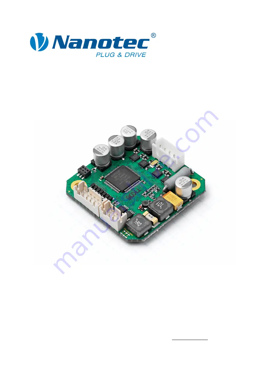
SMCI12
NANOTEC ELECTRONIC GmbH & Co. KG
Gewerbestraße 11
D-85652 Landsham near Munich, Germany
Tel. +49 (0)89-900 686-0
Fax +49 (0)89-900 686-50
[email protected]
The NANOTEC SMCI12 Technical Manual is available for free download from our website. This comprehensive manual provides detailed instructions and information on how to utilize all the advanced features of the SMCI12 product. Get the most out of your NANOTEC SMCI12 with our user-friendly manual.
Technical Manual
Stepper controller
SMCI12
NANOTEC ELECTRONIC GmbH & Co. KG
Gewerbestraße 11
D-85652 Landsham near Munich, Germany
Tel. +49 (0)89-900 686-0
Fax +49 (0)89-900 686-50
[email protected]


