background image

DC200

0A

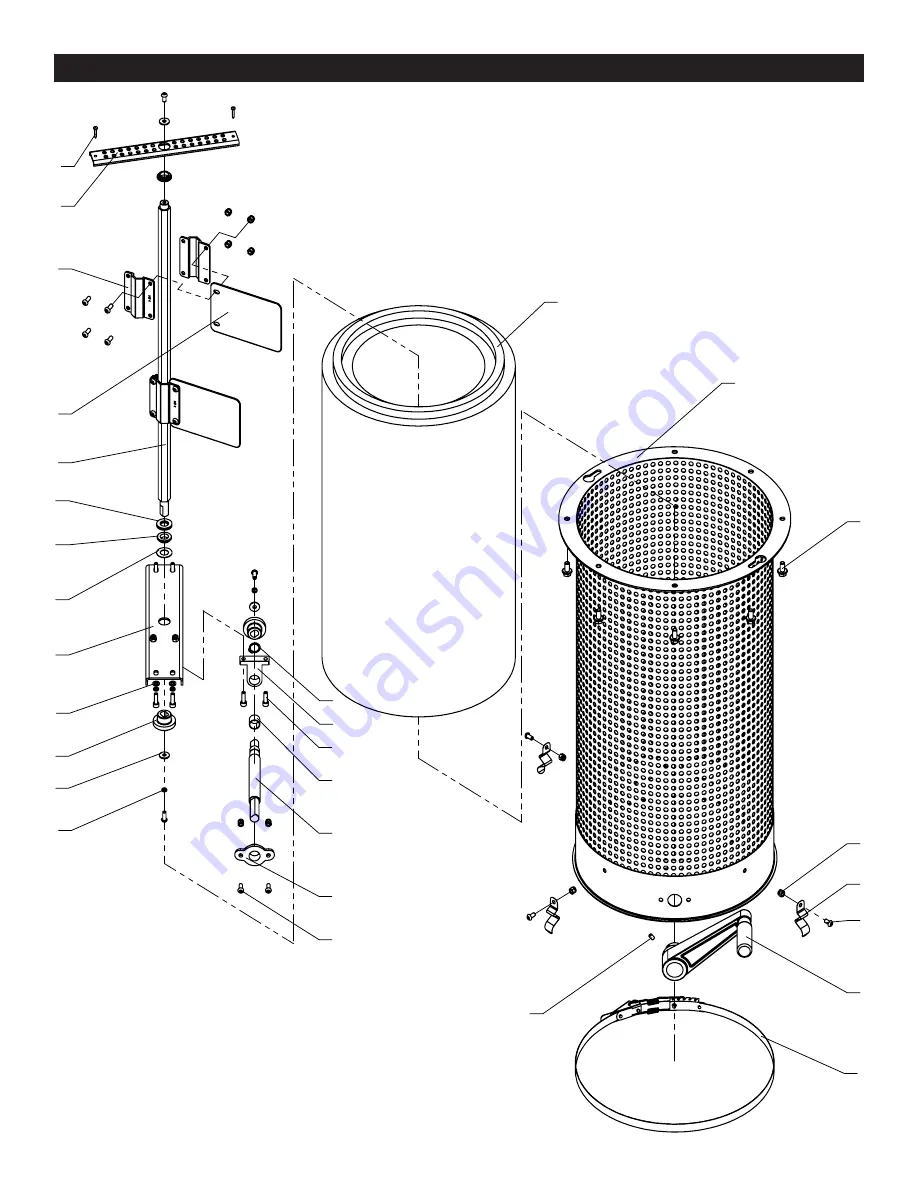
 PARTS DIAGRAM C

1

2

3

4

5

6

7

8

9

10

11

12

13

14

15

17

18

19

21

22

23

24

25

27

26

28

29

20

16

NOTE: 

Please reference the 

Part Number when calling for

Replacement Parts. 

For Parts under Warranty, the Serial 

Number of your machine is required.

14

Summary of Contents for DC2000A

Page 1: ...TORS 2 5HP 1 75HP DC2000A DC3000A Operator s Manual Record the serial number and date of purchase in your manual for future reference The serial number can be found on the specification label on the s...

Page 2: ...ical receptacle The 3rd prong is used to ground the tool and provide protection against accidental electric shock DO NOT remove the 3rd prong See Grounding Instructions on the following pages 4 AVOID...

Page 3: ...ilated area and provide for proper dust removal Use dust collection system wherever possible Exposure to the dust may cause serious and permanent respiratory or other injury including silicosis a seri...

Page 4: ...erstand the grounding instructions or if you are not sure the tool is properly grounded when installing or replacing a plug USE ONLY A 3 WIRE EXTENSION CORD THAT HAS THE PROPER TYPE OF A 3 PRONG GROUN...

Page 5: ...CE A DAMAGED OR WORN CORD OR PLUG IMMEDIATELY IMPROPER ELECTRICAL CONNECTION of the equipment grounding conductor can result in risk of electric shock The conductor with the green insulation with or w...

Page 6: ...chine is unplugged when doing any cleaning assembly setup operations or when not in use 10 DO NOT use the dust collector for collecting liquids substances impregnated with liquids metals gasoline or p...

Page 7: ...machine by means of a metal screw The screw must be threaded into the metal shell to ensure a good connection The grounding of metal duct work is similar wire inside the ducting It can be wrapped alon...

Page 8: ...ir flow in work area 1 Have qualified electrician check circuit for proper line voltage 2 Replace motor capacitor 3 Do not use an extension cord Plug the collector directly into an outlet 4 Clean debr...

Page 9: ...ector bags or cleaning the dust collec tor Please refer to the California Proposition 65 warning on page 6 of this manual regarding hazards from expo sure to wood dust For more detailed information vi...

Page 10: ...12 13 14 15 16 17 18 19 20 21 22 23 24 25 26 27 28 29 31 33 35 30 34 36 37 38 39 45 41 42 43 46 40 44 NOTE Please reference the Part Number when calling for Replacement Parts For Parts under Warranty...

Page 11: ...l Left Support Panel Handle Hex socket head cap screw M8X30 Flat head hex rivet nut M6X15 Switch box assembly Washer 5 Spring washer 4 Cross recessed pan hd screw M4X12 Hex head flange bolt M8X16 Pane...

Page 12: ...DC2000A PARTS DIAGRAM B 1 6 5 2 3 4 7 8 11 10 9 12 NOTE Please reference the Part Number when calling for Replacement Parts For Parts under Warranty the Serial Number of your machine is required 12...

Page 13: ...Hex headed bolt M8X25 Hex socket flat end set screw M8X12 4 1 6 1 4 4 4 1 1 1 1 1 QTY PART NO DESCRIPTION KEY NO P60 1750 1B P60 1750 2B P60 1750 3B P60 1750 4B P60 1750 5B P60 1750 6B P60 1750 7B P60...

Page 14: ...1 2 3 4 5 6 7 8 9 10 11 12 13 14 15 17 18 19 21 22 23 24 25 27 26 28 29 20 16 NOTE Please reference the Part Number when calling for Replacement Parts For Parts under Warranty the Serial Number of you...

Page 15: ...ing Dust remove shaft Dust remove plate Dust remove bracket Upper fixing plate Cross recessed pan head tapping screw 1 1 8 15 3 4 1 1 1 12 1 1 1 6 1 1 6 3 2 4 1 1 2 1 1 2 4 1 2 QTY PART NO DESCRIPTION...

Page 16: ...round hd screw M6X16 Caster wheel Hex flange nut M6 1 16 4 16 QTY PART NO DESCRIPTION KEY NO P60 1750 1D P60 1750 2D P60 1750 3D P60 1750 4D NOTE Please reference the Part Number when calling for Rep...

Page 17: ...DC2000A NOTES Use this section to record maintenance service and any calls to Technical Support 17...

Page 18: ...12 13 14 15 16 17 18 19 20 21 22 23 24 25 26 27 28 29 31 33 35 30 34 36 37 38 39 45 41 42 43 46 40 44 NOTE Please reference the Part Number when calling for Replacement Parts For Parts under Warranty...

Page 19: ...l Left Support Panel Handle Hex socket head cap screw M8X30 Flat head hex rivet nut M6X15 Switch box assembly Washer 5 Spring washer 4 Cross recessed pan hd screw M4X12 Hex head flange bolt M8X16 Pane...

Page 20: ...DC3000A PARTS DIAGRAM B 1 2 3 4 5 6 7 8 11 10 9 12 NOTE Please reference the Part Number when calling for Replacement Parts For Parts under Warranty the Serial Number of your machine is required 20...

Page 21: ...Hex headed bolt M8X25 Hex socket flat end set screw M8X12 4 1 6 1 4 4 4 1 1 1 1 1 QTY PART NO DESCRIPTION KEY NO P60 2500 1B P60 2500 2B P60 2500 3B P60 2500 4B P60 2500 5B P60 2500 6B P60 2500 7B P60...

Page 22: ...1 2 3 4 5 6 7 8 9 10 11 12 13 14 15 17 18 19 21 22 23 24 25 27 26 28 29 20 16 NOTE Please reference the Part Number when calling for Replacement Parts For Parts under Warranty the Serial Number of you...

Page 23: ...ing Dust remove shaft Dust remove plate Dust remove bracket Upper fixing plate Cross recessed pan head tapping screw 1 1 8 15 3 4 1 1 1 12 1 1 1 6 1 1 6 3 2 4 1 1 2 1 1 2 4 1 2 QTY PART NO DESCRIPTION...

Page 24: ...round hd screw M6X16 Caster wheel Hex flange nut M6 1 16 4 16 QTY PART NO DESCRIPTION KEY NO P60 2500 1D P60 2500 2D P60 2500 3D P60 2500 4D NOTE Please reference the Part Number when calling for Rep...

Page 25: ...DC3000A NOTES Use this section to record maintenance service and any calls to Technical Support 25...

Reviews: